


How to Choose a High-Resolution Industrial Lens
09/25/2026
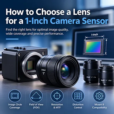
How to Choose a Lens for a 1-Inch Camera Sensor
10/02/2026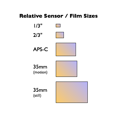
How to Match a Lens to a Camera Sensor is an important question when designing a machine vision, industrial imaging, robotics, or AI camera system. A camera sensor and lens must work together as a complete optical system to deliver sufficient image coverage, resolution, field of view, and reliable imaging performance.
However, matching a lens to a camera sensor involves more than choosing a lens with the same sensor-format label. Engineers also need to consider image circle, sensor dimensions, focal length, field of view (FOV), working distance, resolution, pixel size, distortion, aperture, and lens mount.
This guide explains how to match a lens to a camera sensor step by step. It also provides a practical comparison of common sensor formats, explains how to select lenses for different imaging applications, and shows how to move from camera specifications to an appropriate industrial lens.
If you are new to industrial optics, start with the TOWIN Lens Basics Guide to understand the fundamental relationship between focal length, aperture, field of view, image circle, and other optical parameters.
Why Does Lens-to-Sensor Matching Matter?
The camera sensor and lens perform different but closely connected functions. The lens forms an optical image, while the sensor captures that image and converts it into digital information. If the lens and sensor are poorly matched, the imaging system may not use the sensor effectively or achieve the expected optical performance.
Common problems caused by incorrect lens-to-sensor matching include:
- Vignetting or dark corners
- Incomplete sensor coverage
- Reduced edge sharpness
- Incorrect field of view
- Insufficient optical resolution
- Excessive image distortion
- Reduced measurement accuracy
- Unused camera sensor capability
- Unnecessary system redesign and cost
For machine vision and precision imaging, lens selection should therefore be treated as a system-matching problem rather than a single-parameter decision. TOWIN’s Machine Vision Lens Selection Guide provides a broader selection workflow covering sensor size, FOV, working distance, focal length, resolution, distortion, and environmental requirements.
What Information Do You Need Before Choosing a Lens?
Before selecting an industrial lens, collect the camera and application information that will determine optical compatibility. The more complete these inputs are, the easier it is to identify a suitable lens.
| Parameter | Why It Matters |
|---|---|
| Sensor Size | Determines the active imaging area and required lens coverage. |
| Sensor Dimensions | Used for accurate FOV and image-circle calculations. |
| Resolution | Defines the level of image detail required from the optical system. |
| Pixel Size | Helps determine the optical resolution and MTF requirements. |
| Working Distance | Defines the physical distance between the lens and target. |
| Target Size / Required FOV | Determines how much of the object must be visible in the image. |
| Lens Mount | Ensures mechanical compatibility with the camera. |
| Application | Defines requirements such as distortion, low-light performance, IR correction, or compact size. |
For a detailed explanation of sensor dimensions, pixel size, image formats, and compatibility, see the TOWIN Image Sensor Guide.
Step 1: Identify the Camera Sensor Size
The first step is to identify the camera sensor format and, whenever possible, its actual physical dimensions. Common industrial camera formats include 1/4″, 1/3″, 1/2.8″, 1/2″, 1/1.8″, 2/3″, 1″, and 1.1″.
It is important to remember that these inch-based designations are format names rather than direct measurements of the sensor diagonal. When performing detailed optical matching, use the actual sensor width, height, and diagonal dimensions specified in the camera datasheet.
For example, two cameras may use similar sensor-format terminology while having different active dimensions or aspect ratios. Those differences can affect FOV, image coverage, and lens selection.
The sensor format is therefore the starting point for lens selection, not the final decision.
Step 2: Match the Lens Image Circle to the Sensor
One of the most important checks is whether the lens produces an image circle large enough to cover the camera sensor.
The basic compatibility rule is:
Lens Image Circle ≥ Sensor Imaging Area
If the lens image circle is smaller than the sensor, the outer areas of the sensor may not receive a properly illuminated image. This can produce dark corners, vignetting, loss of image information, or reduced edge performance.
A lens designed for a larger image format can generally be used with a smaller sensor when the mechanical and optical requirements are also compatible. The smaller sensor simply uses a smaller portion of the available image circle. The reverse is not normally true: a lens designed for a smaller format may not fully cover a larger sensor.
| Camera Sensor | Lens Coverage Requirement | Typical Lens Direction |
|---|---|---|
| 1/4″ | ≥ 1/4″ sensor coverage | M12 / Compact Lens |
| 1/3″ | ≥ 1/3″ sensor coverage | M12 Lens |
| 1/2″ | ≥ 1/2″ sensor coverage | M12 / C-Mount |
| 1/1.8″ | ≥ 1/1.8″ sensor coverage | High-Resolution M12 / C-Mount |
| 2/3″ | ≥ 2/3″ sensor coverage | FA / C-Mount |
| 1″ | ≥ 1″ sensor coverage | Large-Format C-Mount |
These are general selection directions rather than universal specifications. Always verify the actual sensor dimensions and usable image circle in the camera and lens datasheets.
For a deeper explanation of image-circle compatibility, see What Is Image Circle in an Industrial Lens?
Step 3: Match Sensor Size With Lens Format
Sensor size and lens format are closely related, but they are not exactly the same specification.
Sensor size describes the imaging area of the camera, while lens format describes the sensor area that the optical design is intended to cover.
| Parameter | What It Describes | Examples |
|---|---|---|
| Sensor Size | Camera imaging area | 1/3″, 1/1.8″, 2/3″, 1″ |
| Lens Format | Optical coverage | 1/3″, 1/2″, 2/3″, 1″ |
| Lens Mount | Mechanical camera interface | M12, C-Mount, CS-Mount |
For example, a C-Mount lens may be designed for a 2/3″ sensor while another C-Mount lens may be designed for a 1″ or 1.1″ sensor. The mount is the same, but the optical coverage is different.
Therefore, do not select a lens simply because the mount fits the camera. Confirm both the mechanical interface and the optical image coverage.
Step 4: Determine Field of View and Focal Length
After confirming sensor coverage, the next question is whether the lens can capture the required target area.
Field of view depends mainly on:
- Sensor dimensions
- Lens focal length
- Working distance
In general:
- Shorter focal length → wider FOV
- Longer focal length → narrower FOV and greater magnification
This means that a lens can be perfectly compatible with a sensor but still be unsuitable for the application because the field of view is too narrow or too wide.
For example, a 12mm lens used with different sensor formats will not necessarily produce the same field of view. A larger sensor captures a larger portion of the lens image, which generally results in a wider FOV.
To estimate the required viewing area before choosing a lens, use the TOWIN FOV Calculator. The tool can be used to evaluate field of view based on sensor dimensions, focal length, and working distance.
You can also learn more about the relationship between these parameters in How Does Focal Length Affect Field of View? and How to Calculate Field of View for a Camera Lens.
Step 5: Match Lens Resolution With Sensor Resolution
A high-resolution camera does not automatically produce a high-resolution image. The lens must also provide sufficient resolving power to take advantage of the sensor.
When evaluating lens resolution, consider more than the megapixel number printed on the product specification. Important factors include pixel size, MTF, edge performance, optical aberrations, and the imaging requirements of the application.
| Camera Requirement | Lens Requirement |
|---|---|
| High-resolution sensor | High optical resolving power |
| Small pixel size | Higher optical resolution and strong MTF performance |
| Precision measurement | High resolution with controlled distortion |
| Large-format sensor | Consistent image quality across the required image circle |
For example, TOWIN’s large-format C-Mount range includes 1.1″ 20MP machine vision lenses for high-resolution industrial imaging. Such lenses are designed around large sensors and high-resolution requirements rather than simply providing a compatible mechanical mount.
For a more detailed high-resolution selection process, read How to Choose a High-Resolution Industrial Lens.
You can also refer to the Optical Design Guide to learn more about MTF, optical resolution, aberrations, and image quality.
Step 6: Check Lens Mount Compatibility
Even when the optical parameters are correct, the lens must also be mechanically compatible with the camera.
Common industrial and embedded imaging interfaces include M12, C-Mount, and CS-Mount.
| Mount | Typical Direction | Common Applications |
|---|---|---|
| M12 | Compact optical systems | Embedded Vision, Robotics, AI Cameras |
| C-Mount | Industrial optical systems | Machine Vision, Inspection, High-Resolution Imaging |
| CS-Mount | Compact camera and security systems | Surveillance, IP Cameras, Security Imaging |
The mount should be considered together with sensor coverage, focal length, back focal requirements, mechanical clearance, and the intended application.
For compact embedded systems, explore TOWIN M12 Lenses; For industrial inspection and larger sensor applications, explore TOWIN C-Mount Lenses.
For security and IP camera systems, see TOWIN CS-Mount Lenses.
Step 7: Consider the Application Before Selecting the Final Lens
Sensor compatibility is only one part of lens selection. The same sensor may require very different lenses depending on the application.
Machine Vision
Machine vision systems often require high resolution, controlled distortion, stable imaging, and accurate field of view. Inspection and measurement applications may place particular emphasis on edge performance and geometric accuracy.
Explore TOWIN’s Machine Vision Lens Solutions for industrial inspection, measurement, automation, barcode scanning, and defect detection applications.
Robotics Vision
Robotics and embedded vision systems may prioritize compact dimensions, wide FOV, low distortion, and reliable imaging at relatively short working distances.
See Robotics Vision Solutions for AGV, AMR, SLAM, robot navigation, and AI vision applications.
Smart Security
Security cameras may require wide-area coverage, low-light performance, IR correction, or day-and-night imaging. The lens should therefore be selected according to both the camera sensor and the environmental imaging conditions.
Explore Smart Security Lens Solutions for AI surveillance, CCTV, face recognition, human detection, and low-light applications.
ADAS and Automotive Vision
Automotive imaging systems can require wide FOV, IR compatibility, low distortion, high transmittance, and environmental robustness. Sensor matching should therefore be evaluated together with wavelength and application-specific requirements.
Learn more about ADAS Lens Solutions for surround-view, driver monitoring, and automotive vision systems.
Smart Traffic
Traffic monitoring and ANPR systems may require long-distance imaging, appropriate focal length, low distortion, IR performance, and reliable imaging in outdoor environments.
See Smart Traffic Lens Solutions for traffic monitoring, ANPR, intelligent transportation, and related imaging applications.
How to Choose the Right Lens for Different Sensor Sizes
The following table provides a practical starting point for matching common sensor formats with suitable lens directions. These are general guidelines; final selection should always be based on the actual camera and lens specifications.
| Sensor Format | Typical Lens Direction | Key Parameters | Typical Applications |
|---|---|---|---|
| 1/4″ – 1/3″ | M12 / Compact Lens | FOV, distortion, size, resolution | Embedded Vision, AI Cameras |
| 1/2.8″ – 1/2″ | M12 / C-Mount | FOV, resolution, image circle | Robotics, Security, Embedded Vision |
| 1/1.8″ | High-Resolution M12 / C-Mount | Resolution, MTF, distortion | Machine Vision, AI Vision |
| 2/3″ | FA / C-Mount | MTF, distortion, working distance | Industrial Inspection |
| 1″ | Large-Format C-Mount | Image circle, resolution, FOV | Precision Imaging, Machine Vision |
| 1.1″ | High-Resolution C-Mount / FA Lens | 20MP+, image circle, edge performance | High-Resolution Inspection |
Practical Lens Selection Examples
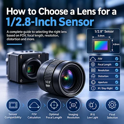
Example 1: 1/2.8″ 8MP Camera With an M12 Mount
Suppose an embedded vision camera uses a 1/2.8″ 8MP sensor and requires a relatively wide field of view. The selection process should begin by confirming the actual sensor dimensions and ensuring that the selected M12 lens provides sufficient image coverage.
Next, determine the target size and working distance. These values can be entered into the TOWIN FOV Calculator to estimate the required focal length.
Finally, verify optical resolution, distortion, aperture, minimum object distance, and mechanical dimensions before choosing the final lens.
For compact applications, the TOWIN M12 Lens Solution provides a range of optical configurations for machine vision, robotics, AI cameras, security, and other embedded imaging applications.
Example 2: 2/3″ 5MP Machine Vision Camera
A 2/3″ 5MP machine vision camera may require a C-Mount or FA lens with sufficient sensor coverage and appropriate optical resolution.
If the application involves dimensional inspection, distortion should be considered together with FOV and working distance. A lens that provides sufficient sensor coverage but excessive geometric distortion may not be appropriate for precision measurement.
TOWIN offers C-Mount and FA lens configurations for 2/3″ machine vision applications, including lenses designed around resolution and low-distortion requirements.
For more information about geometric distortion and why it matters in machine vision, see the TOWIN Distortion Guide.
Example 3: 1″ or 1.1″ High-Resolution Camera
Larger sensors require a lens with sufficient image-circle coverage and consistent optical performance across the imaging area. For a high-resolution 1.1″ camera, the lens must also provide enough resolving power to take advantage of the sensor’s pixel density.
TOWIN’s 1.1″ 20MP Machine Vision Lens range includes C-Mount and FA configurations designed for high-resolution industrial imaging.
Depending on the application, engineers can select different focal lengths to achieve the required FOV while considering distortion, aperture, working distance, and edge performance.
Lens and Sensor Matching Comparison
| Selection Stage | Question to Ask | What to Check |
|---|---|---|
| 1. Sensor | What camera sensor am I using? | Sensor format, width, height, diagonal |
| 2. Coverage | Does the lens cover the entire sensor? | Image circle / lens format |
| 3. FOV | How much of the target must be visible? | Target size, sensor dimensions, FOV |
| 4. Focal Length | What focal length provides the required FOV? | Focal length and working distance |
| 5. Resolution | Can the lens resolve the sensor detail? | Resolution, pixel size, MTF |
| 6. Distortion | How much geometric distortion is acceptable? | TV distortion / application requirements |
| 7. Mount | Can the lens physically connect to the camera? | M12, C-Mount, CS-Mount, flange requirements |
| 8. Application | What operating conditions must the lens handle? | Lighting, IR, temperature, vibration, size, environment |
Common Lens-to-Sensor Matching Mistakes
1. Choosing a Lens Only by Focal Length
Focal length determines an important part of the FOV relationship, but it does not tell you whether the lens adequately covers the sensor. Always check image circle and sensor format as well.
2. Ignoring Image Circle
A lens with an insufficient image circle can produce vignetting, dark corners, and incomplete image coverage. Image-circle verification should be one of the first checks in the selection process.
3. Using a Smaller-Format Lens on a Larger Sensor
A lens designed for a smaller sensor format may not cover a larger sensor. A larger-format lens can generally be considered for a smaller sensor when the complete optical and mechanical specifications are compatible.
4. Matching Megapixels but Ignoring Optical Resolution
A 20MP camera does not guarantee 20MP-level image detail if the lens cannot resolve the required spatial information. Sensor resolution, pixel size, lens resolution, and MTF should be considered together.
5. Confusing Lens Mount With Lens Format
M12, C-Mount, and CS-Mount describe mechanical interfaces. They do not by themselves guarantee sufficient optical coverage for a particular sensor.
6. Skipping FOV Verification
Even when the lens and sensor are optically compatible, the selected focal length may not provide the required target coverage. Always verify FOV using the actual sensor dimensions and working distance.
Lens Selection Checklist
Before finalizing an industrial lens, use this checklist:
- Confirm the camera sensor format.
- Record the actual sensor width and height.
- Check sensor resolution and pixel size.
- Confirm that the lens image circle covers the sensor.
- Define the required target size and FOV.
- Measure or confirm the working distance.
- Calculate the required focal length.
- Check lens resolution and MTF requirements.
- Evaluate distortion according to the application.
- Confirm aperture and lighting requirements.
- Verify M.O.D. and focusing requirements.
- Confirm the mechanical mount and installation space.
- Consider environmental and wavelength requirements.
- Prototype and test the complete camera-lens system under real conditions.
If you need a broader step-by-step workflow, use the TOWIN Machine Vision Lens Selection Guide before moving to the final product selection.
Frequently Asked Questions
Q1: Can any lens be used with a camera that has the same sensor size?
A: No. The sensor-format label is only one compatibility factor. You should also check image circle, focal length, FOV, resolution, distortion, aperture, working distance, and lens mount.
Q2: What happens if the lens image circle is smaller than the camera sensor?
A: The lens may not fully illuminate the sensor. This can cause vignetting, dark corners, incomplete image coverage, and reduced edge performance.
Q3: Can I use a 1″ lens on a smaller sensor?
A: A larger-format lens can generally cover a smaller sensor because the smaller sensor uses only part of the available image circle. However, the mount, focal length, working distance, optical performance, and mechanical dimensions must still be compatible.
Q4: Does sensor size determine focal length?
A: Sensor size affects the resulting field of view, but it does not independently determine focal length. Focal length should be selected according to sensor dimensions, required FOV, target size, and working distance.
Q5: How do I choose a lens for an 8MP or 20MP camera?
A: Start with sensor size and pixel size, then verify the lens’s optical resolution, MTF, image circle, distortion, and FOV. A high-megapixel camera generally requires a lens capable of resolving the required image detail.
Q6: What is the difference between lens format and lens mount?
A: Lens format describes the sensor area that the optical design is intended to cover. Lens mount describes the mechanical interface between the lens and camera. A C-Mount lens, for example, can be designed for different sensor formats.
Q7: Should I choose an M12, C-Mount, or CS-Mount lens?
A: The choice depends on the camera interface, sensor size, optical requirements, physical space, and application. M12 lenses are commonly used in compact embedded and robotics systems, C-Mount lenses are widely used in industrial machine vision, and CS-Mount lenses are common in security and IP camera systems.
Q8: What information should I provide when requesting a lens recommendation?
A: Provide the sensor model or sensor size, resolution, pixel size, required FOV or target size, working distance, mount type, application, distortion requirements, lighting conditions, and any mechanical size constraints. These details allow a lens supplier to evaluate the complete optical system rather than recommending a lens based on only one parameter.
Conclusion: Match the Lens to the Complete Imaging System
How to Match a Lens to a Camera Sensor is not simply a matter of finding a lens with the same sensor-format label. A reliable industrial imaging system requires the camera and lens to be evaluated as a complete optical system.
The most important starting point is to confirm that the lens image circle fully covers the sensor. After that, engineers should evaluate FOV, focal length, working distance, resolution, pixel size, distortion, aperture, lens mount, and application requirements.
The complete lens-to-sensor matching process can be summarized as:
Sensor Size → Sensor Dimensions → Image Circle → Lens Format → FOV → Focal Length → Resolution → Distortion → Mount → Application → Final Lens Selection
If you already know your camera sensor, target size, and working distance, start with the TOWIN FOV Calculator to estimate the required viewing area and focal length. You can then use the Machine Vision Lens Selection Guide to evaluate the remaining optical parameters.
For compact embedded and robotics applications, explore TOWIN M12 Lenses. For industrial inspection and high-resolution imaging, review TOWIN C-Mount Lenses and the 1.1″ 20MP Machine Vision Lens range.
Ultimately, How to Match a Lens to a Camera Sensor means matching the lens not only to the sensor, but to the entire imaging system. A properly matched optical system can help reduce vignetting, preserve image detail, achieve the required FOV, and improve the reliability of machine vision and industrial imaging applications.
Need Help Matching a Lens to Your Camera Sensor?
If you are unsure which lens is compatible with your camera sensor, prepare the following information:
- Sensor size or sensor model
- Camera resolution and pixel size
- Target size
- Working distance
- Required horizontal or diagonal FOV
- Lens mount
- Application
- Distortion requirement
- Lighting and environmental conditions
- Mechanical size restrictions
With these parameters, TOWIN can evaluate image-circle coverage, focal length, FOV, resolution, distortion, mount, and application requirements to identify a suitable industrial lens configuration.
Ready to select the right lens for your camera sensor?
Start with the TOWIN Lens Selection Guide or use the FOV Calculator to begin your lens selection process.