


How to Match a Camera Lens to Sensor Size
08/21/2026
Why Is Low Distortion Important in Machine Vision?
08/28/2026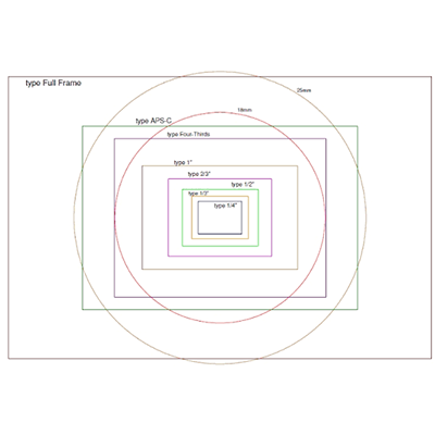
What Is Image Circle in an Industrial Lens? Image circle is one of the fundamental optical parameters engineers need to understand when selecting an industrial or machine vision lens. It describes the circular image area projected by a lens onto the camera sensor plane and determines whether the lens can fully cover the sensor.
A correct image circle match is essential for achieving complete image coverage, consistent illumination, and reliable image quality. If the image circle is too small for the sensor, the system may suffer from vignetting, dark corners, reduced usable image area, or inaccurate measurements.
In this guide, we explain what image circle means, how it relates to sensor size and sensor diagonal, why image circle matters for industrial lens selection, and how to match an industrial lens to a camera sensor. We will also compare image circle with lens format and lens mount, explain common matching mistakes, and show how image circle fits into a complete lens selection process.
Quick Answer
Image circle is the circular area of usable image projected by an industrial lens onto the camera sensor plane. To achieve complete sensor coverage, the usable image circle should be equal to or larger than the sensor’s diagonal. If the image circle is too small, the image may show vignetting, dark corners, or incomplete sensor coverage.
What Is Image Circle in an Industrial Lens?
An image circle is the circular area of usable optical information formed by a lens at the image plane. Although camera sensors are normally rectangular, the optical system projects a circular image onto the sensor plane.
The camera sensor captures the portion of this projected image that falls within its active area. For full-frame sensor coverage, the entire rectangular sensor must fit inside the usable image circle.
This creates a basic relationship between the lens and sensor:
Image Circle Diameter ≥ Sensor Diagonal
For example, if a camera sensor has a diagonal of approximately 8 mm, the lens should provide an image circle that is large enough to cover that diagonal. A lens with insufficient image circle coverage may illuminate the center of the sensor while leaving the corners poorly illuminated or outside the usable image area.
Image circle should not be confused with focal length. Focal length primarily determines the relationship between the lens, sensor, working distance, and field of view, while image circle determines whether the lens provides sufficient optical coverage for the sensor.
If you are new to industrial optics, start with the Lens Basics for Machine Vision and Industrial Cameras to understand focal length, aperture, sensor size, FOV, image circle, distortion, and other fundamental optical parameters.
How Does Image Circle Work?
Every lens projects an image onto the image plane. In an idealized optical system, this image is circular. The camera sensor, however, normally has a rectangular active area.
The relationship can be simplified as:
            Lens Image Circle
        _________________________
      /                           \
     /                             \
    |       ┌─────────────┐        |
    |       │             │        |
    |       │   SENSOR    │        |
    |       │             │        |
    |       └─────────────┘        |
     \                             /
      \___________________________/
The sensor should remain completely inside the usable image circle to achieve full image coverage.
When the sensor is smaller than the available image circle, the lens can generally provide complete coverage. When the sensor is larger than the usable image circle, the sensor extends beyond the area where the lens can provide sufficient image information.
This is why image circle is one of the first optical compatibility checks when matching an industrial lens with a camera.
Why Is Image Circle Important in Industrial Lens Selection?
Image circle compatibility directly affects whether the camera can use the complete active area of its sensor. A lens may have excellent resolution and low distortion, but if its image circle is too small, the overall imaging system can still perform poorly.
| Image Circle Requirement | Potential Result |
|---|---|
| Image circle fully covers sensor | Complete image coverage |
| Image circle is approximately equal to sensor diagonal | Coverage may be sufficient, subject to optical design and specifications |
| Image circle is smaller than sensor diagonal | Vignetting, dark corners, or incomplete image coverage may occur |
| Image circle is significantly larger than sensor | Sensor is fully covered, but larger image circle alone does not guarantee better image quality |
Correct image circle matching can help ensure full sensor utilization, consistent illumination, and reliable image information across the frame. It is particularly important in machine vision inspection, robotics, AI imaging, smart traffic, and measurement systems.
Image Circle vs Sensor Size
Image circle and sensor size are closely related, but they describe two different parts of the imaging system. Sensor size describes the physical active area of the camera sensor, while image circle describes the optical coverage provided by the lens.
The sensor must fit inside the lens image circle for complete coverage. Because the sensor is rectangular, its diagonal is especially important when determining the minimum required image circle.
Sensor Diagonal and Image Circle
The sensor diagonal can be calculated from the active sensor width and height:
Sensor Diagonal = √(Sensor Width² + Sensor Height²)
For example, if the active sensor area is 6.4 mm wide and 4.8 mm high:
Sensor Diagonal = √(6.4² + 4.8²)
Sensor Diagonal ≈ 8.0 mm
A lens intended to provide full coverage for this sensor therefore needs an image circle large enough to cover approximately 8 mm of diagonal. Actual lens specifications should always be checked because the usable optical coverage depends on the lens design and manufacturer specifications.
For a deeper explanation of sensor formats, active sensor dimensions, pixel size, resolution, and lens compatibility, visit the Industrial Camera Sensor Guide.
What Happens When the Image Circle Is Too Small?
When the image circle is smaller than the sensor, the corners of the sensor may extend outside the usable optical image. This can result in several problems.
- Dark corners or corner shading
- Vignetting
- Incomplete sensor coverage
- Reduced usable image area
- Reduced edge performance
- Potential measurement errors
In a machine vision system, these problems can be particularly serious because the edges of the image may contain important inspection features. Losing usable information near the sensor corners can reduce system reliability.
What Happens When the Image Circle Is Larger Than the Sensor?
A larger image circle generally means that the lens provides sufficient optical coverage for the sensor. A lens designed for a larger sensor can often be used with a smaller sensor, provided that other optical and mechanical requirements are also satisfied.
However, a larger image circle does not automatically mean higher resolution, lower distortion, or better image quality. Image circle primarily addresses optical coverage. Resolution, MTF, distortion, aperture, illumination, and other lens parameters must still be evaluated separately.
How to Match Image Circle to a Camera Sensor
Matching image circle to a camera sensor is one of the first steps in lens selection. A practical workflow can be divided into four steps.
Step 1: Identify the Sensor Format
Start by identifying the camera sensor format, such as 1/4″, 1/3″, 1/2″, 2/3″, 1/1.8″, or 1″. These format names provide a useful reference, but they should not be treated as exact physical dimensions.
Sensor dimensions can vary depending on the sensor design and aspect ratio, so the actual active width and height should be checked whenever accurate optical matching is required.
Step 2: Find the Actual Sensor Dimensions
Look for the sensor’s active width and height in the camera or sensor datasheet. These values are more useful than relying only on a nominal sensor format.
For example:
| Sensor Parameter | Example |
|---|---|
| Sensor Format | 1/2″ |
| Active Width | 6.4 mm |
| Active Height | 4.8 mm |
| Sensor Diagonal | Approximately 8.0 mm |
Step 3: Calculate or Confirm the Sensor Diagonal
Use the sensor width and height to calculate the diagonal:
Diagonal = √(Width² + Height²)
This diagonal provides a practical reference for evaluating whether the lens image circle is large enough to cover the sensor.
Step 4: Check the Lens Image Circle
Finally, compare the lens image circle with the sensor diagonal and verify the manufacturer’s lens specification.
Required Lens Coverage ≥ Sensor Diagonal
If the lens is specified for a sensor format equal to or larger than the camera sensor, it may provide sufficient coverage. However, the actual lens datasheet should always be checked for the supported image format and optical performance.
For a complete step-by-step lens-to-sensor matching workflow, see How to Match a Camera Lens to Sensor Size.
Image Circle Comparison by Sensor Size
Different sensor formats require different levels of optical coverage. The following table provides general reference values for common industrial camera formats. Actual requirements should be verified using the camera’s active sensor dimensions.
| Sensor Format | Approximate Image Circle Requirement | Common Lens Type | Typical Applications |
|---|---|---|---|
| 1/4″ | Approximately 4–5 mm | M12 Lens | Embedded Vision, Compact Cameras |
| 1/3″ | Approximately 6 mm | M12 Lens | Security, AI Vision, Embedded Imaging |
| 1/2″ | Approximately 8 mm | M12 / FA Lens | Machine Vision, Robotics |
| 2/3″ | Approximately 11 mm | FA / C-Mount Lens | Industrial Inspection |
| 1″ | Approximately 16 mm | C-Mount / FA Lens | Precision Imaging, Smart Traffic |
These values are general references rather than universal specifications. The actual sensor diagonal, aspect ratio, active imaging area, and lens design should be checked before final selection.
TOWIN’s Sensor Guide provides additional information about sensor formats, sensor dimensions, pixel characteristics, and lens matching.
Image Circle vs Lens Format vs Lens Mount
One of the most common mistakes in industrial lens selection is treating image circle, lens format, and lens mount as the same specification. They describe different aspects of the camera-lens system.
| Parameter | What It Describes | Examples |
|---|---|---|
| Image Circle | Optical coverage provided by the lens | 8 mm, 11 mm, 16 mm+ |
| Lens Format | Approximate sensor format the optical design is intended to cover | 1/3″, 1/2″, 2/3″, 1″ |
| Sensor Format | Camera sensor classification | 1/2″, 2/3″, 1″ |
| Lens Mount | Mechanical interface between lens and camera | M12, C-Mount, CS-Mount |
For example, an M12 lens does not automatically mean that it is designed for one specific sensor size. M12 describes the mechanical mount, while the lens optical design determines its image circle, sensor coverage, focal length, FOV, and other optical characteristics.
For a detailed comparison of M12, CS-Mount, and C-Mount systems, see the M12, CS, and C-Mount Lens Selection Guide.
Image Circle and Vignetting
Vignetting refers to a reduction in brightness or usable image information toward the edges or corners of an image. An insufficient image circle is one possible cause of strong corner shading.
Correct Image Circle Matching
- Full sensor coverage
- Complete image information
- Reduced risk of dark corners
- Better utilization of the sensor area
- More reliable inspection results
Insufficient Image Circle
- Dark corners
- Vignetting
- Reduced usable sensor area
- Loss of image information near the edges
- Potential measurement problems
However, image circle is not the only factor that can influence vignetting. Optical design, aperture, mechanical structures, filters, sensor characteristics, and other system components can also affect edge illumination.
Does Image Circle Affect Field of View?
Image circle does not directly determine focal length or angular field of view. However, image circle and sensor size are closely related to how much of the projected image the camera can actually use.
If the lens does not fully cover the sensor, the camera may not be able to use the complete sensor area. This can reduce the effective image coverage and create edge shading or cropping.
Field of view itself depends primarily on the relationship between sensor size, focal length, and working distance. If you want to understand how these parameters are used to calculate FOV, read How to Calculate Field of View for a Camera Lens.
You can also use the TOWIN FOV Calculator to estimate horizontal, vertical, and diagonal field of view based on your camera and lens parameters.
Does a Larger Image Circle Mean Better Image Quality?
Not necessarily. A larger image circle primarily means that the lens provides a larger optical coverage area. It does not automatically mean that the lens has higher resolution, better MTF, lower distortion, or superior overall image quality.
For example, a lens with a large image circle may adequately cover a 1″ sensor, but the optical resolution still needs to be high enough to support the camera’s pixel size and resolution.
Industrial lens performance should therefore be evaluated as a complete optical system.
| Lens Parameter | Primary Function |
|---|---|
| Image Circle | Sensor coverage |
| Focal Length | FOV and magnification |
| Resolution / MTF | Fine detail and image sharpness |
| Distortion | Geometric accuracy |
| Aperture | Light transmission and depth of field |
| Working Distance | Camera-to-target relationship |
| Mount | Mechanical camera compatibility |
For a broader overview of these parameters and how they work together, visit the Industrial Lens Selection Guide.
How to Choose an Industrial Lens Based on Image Circle
Image circle is an important starting point, but it should not be the only criterion used when choosing an industrial lens. A practical selection process should consider sensor compatibility, FOV, focal length, working distance, resolution, distortion, aperture, mount, and application requirements.
M12 Lenses
M12 lenses are compact optical solutions commonly used with embedded cameras, robotics systems, AI cameras, smart devices, and other space-constrained imaging platforms. TOWIN’s M12 lens range includes different sensor formats, focal lengths, FOV options, and optical configurations.
When selecting an M12 lens, verify the supported sensor format and image circle rather than choosing based on the M12 mount alone.
Explore TOWIN M12 Lenses for compact industrial imaging applications.
C-Mount Lenses
In practical applications, C‑Mount lenses are widely used in industrial cameras and machine vision systems where larger sensors, higher optical performance, and flexible lens configurations are required.
C-Mount designs are available for a range of sensor formats, including 1/1.8″, 2/3″, 1″, and larger formats. The correct lens should be selected according to the actual sensor coverage, focal length, FOV, resolution, and working distance.
Explore TOWIN C-Mount Lenses for machine vision and industrial imaging applications.
CS-Mount Lenses
CS-Mount lenses are commonly used in compact cameras, surveillance systems, network cameras, and other imaging devices. Like M12 and C-Mount systems, the CS mount describes the mechanical interface rather than the image circle itself.
Always verify both mechanical compatibility and optical sensor coverage before selecting a CS-Mount lens.
FA and Machine Vision Lenses
FA and machine vision lenses are designed for industrial inspection, automation, measurement, and other applications where consistent optical performance is important. These systems often require careful matching of sensor size, image circle, resolution, FOV, distortion, and working distance.
If you need to evaluate multiple parameters at the same time, use TOWIN’s Industrial Lens Selection Guide to work through the lens selection process step by step.
Image Circle Requirements for Different Applications
Image circle requirements vary according to the camera sensor and optical configuration used in each application. The same principle applies across machine vision, robotics, smart traffic, and AI imaging: the lens must provide sufficient optical coverage for the active sensor area.
Machine Vision Inspection
Machine vision systems often use medium or large sensors to capture detailed images of components, products, or inspection areas. Image circle must be large enough to cover the entire sensor while the lens also provides sufficient resolution and acceptable distortion.
Robotics Vision
Robotics applications may use compact sensors and M12 lenses or larger industrial cameras with C-Mount lenses. The lens must balance image circle, FOV, distortion, and working distance so that objects can be detected and positioned reliably.
Smart Traffic
Smart traffic and ANPR systems may use larger sensors and longer focal lengths depending on the installation distance and target size. Image circle must still fully cover the active sensor to maintain the intended imaging area.
AI Cameras
AI cameras often use compact imaging modules, where M12 lenses are frequently considered. The image circle must match the sensor while the lens also provides adequate resolution and FOV for the target objects.
Common Image Circle Matching Mistakes
1. Assuming the Lens Mount Determines Image Circle
M12, C-Mount, and CS-Mount describe mechanical interfaces. They do not by themselves define the optical sensor coverage. Two lenses with the same mount can have different sensor compatibility and image circles.
2. Matching Only the Nominal Sensor Format
A sensor format such as 1/2″ is useful for initial selection, but the actual active sensor dimensions should be checked when accurate optical matching is required.
3. Ignoring Sensor Diagonal
Because the sensor is rectangular, checking only its width may not be sufficient. The lens must provide enough usable image circle to cover the sensor’s diagonal.
4. Assuming a Larger Image Circle Means Higher Resolution
Image circle and optical resolution describe different properties. A larger image circle does not automatically mean that the lens can resolve more detail.
5. Ignoring Vignetting
If the image circle does not adequately cover the sensor, dark corners or reduced illumination may occur. This is particularly important when the entire sensor area is required for inspection or measurement.
6. Choosing a Lens Based Only on Image Circle
Image circle is only one part of lens selection. FOV, focal length, working distance, resolution, distortion, aperture, mount, environmental conditions, and application requirements should also be considered.
Image Circle and Other Industrial Lens Parameters
Image circle should be evaluated as part of a complete optical system rather than as an isolated specification.
| Parameter | Main Question | Why It Matters |
|---|---|---|
| Image Circle | Does the lens cover the sensor? | Prevents incomplete coverage and vignetting |
| Sensor Size | How large is the active imaging area? | Determines required optical coverage and FOV |
| Focal Length | How wide or narrow should the view be? | Controls FOV and magnification |
| Working Distance | How far is the target from the camera? | Influences focal length and image scale |
| Resolution / MTF | Can the lens resolve sensor detail? | Determines image sharpness and fine-detail performance |
| Distortion | How accurately are shapes reproduced? | Important for measurement and positioning |
| Aperture | How much light enters the lens? | Affects exposure and depth of field |
| Mount | Will the lens physically connect to the camera? | Ensures mechanical compatibility |
For precision applications where distortion is especially important, see the Industrial Lens Distortion Guide.
Frequently Asked Questions
Q: What is image circle in an industrial lens?
A: Image circle is the circular area of usable image projected by an industrial lens onto the sensor plane. The sensor should fit completely within this usable optical area to achieve full image coverage.
Q: Why does the image circle need to cover the sensor diagonal?
A: A camera sensor is typically rectangular, so its diagonal is longer than either its width or height. The lens image circle needs to cover this diagonal to provide complete coverage of the sensor corners.
Q: What happens if the image circle is too small?
A: An undersized image circle can cause vignetting, dark corners, incomplete image coverage, reduced usable sensor area, and potentially lower measurement accuracy.
Q: Is image circle the same as lens format?
A: No. Image circle describes the optical coverage provided by the lens, while lens format generally indicates the sensor format the lens is designed to cover. The two specifications are related but are not identical.
Q: Is image circle the same as lens mount?
A: No. Lens mount describes the mechanical interface between the lens and camera, such as M12, C-Mount, or CS-Mount. Image circle describes optical sensor coverage.
Q: Does a larger image circle improve image quality?
A: Not by itself. A larger image circle can provide sufficient sensor coverage, but image quality also depends on resolution, MTF, distortion, aperture, illumination, optical design, and sensor characteristics.
Q: Can one industrial lens support multiple sensor sizes?
A: Yes. If the lens provides sufficient image circle coverage, a lens designed for a larger sensor can often be used with smaller sensors. However, focal length, FOV, resolution, distortion, and other optical requirements must still be checked.
Q: How do I match an industrial lens to my sensor?
A: Start by identifying the sensor’s actual active dimensions, calculate or confirm its diagonal, and verify that the lens provides sufficient image circle coverage. Then evaluate FOV, focal length, working distance, resolution, distortion, aperture, and mount compatibility. See the Industrial Lens Selection Guide for the complete selection process.
Conclusion
Understanding What Is Image Circle in an Industrial Lens is essential for selecting a lens that can properly match a machine vision or industrial camera sensor. Image circle represents the usable circular image area projected by the lens, while the camera sensor has a rectangular active area. For complete image coverage, the usable image circle should be large enough to cover the sensor’s diagonal.
A correct image circle match helps prevent vignetting, dark corners, incomplete sensor coverage, and potential measurement problems. However, image circle should never be considered alone. FOV, focal length, working distance, resolution, MTF, distortion, aperture, and lens mount all contribute to the final performance of an industrial imaging system.
If you are selecting a lens for a new camera system, start by confirming the sensor size and image circle compatibility, then determine the required FOV and other optical parameters. You can use the TOWIN FOV Calculator to calculate the required field of view and continue with the Industrial Lens Selection Guide to identify the right lens configuration.
Ultimately, What Is Image Circle in an Industrial Lens is not just a basic optical question. It is one of the first compatibility checks that connects the camera sensor, lens design, image coverage, and overall machine vision performance.
Need Help Selecting the Right Industrial Lens?
Match your sensor, image circle, FOV, resolution, and working distance before choosing a lens. TOWIN provides standard industrial lenses as well as OEM/ODM optical solutions for machine vision, robotics, AI imaging, smart traffic, and other industrial applications.