


Common Industrial Camera Lens Selection Mistakes
10/20/2026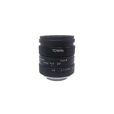
Machine Vision Camera Lens Selection is an essential step in building a reliable industrial vision system. The right lens helps a camera capture the required field of view, resolve important image details, and deliver consistent image quality for automated inspection, measurement, identification, and robot guidance. Even a high-resolution camera may fail to deliver the expected results if its lens is poorly matched to the sensor or application.
Choosing a machine vision lens involves more than comparing focal lengths or megapixel ratings. Engineers must consider sensor size, image circle, field of view (FOV), working distance (WD), optical resolution, distortion, aperture, depth of field, mounting compatibility, and operating conditions.
This guide explains how to evaluate these parameters, compare common industrial lens types, and follow a practical selection process. It also introduces useful resources and product categories from TOWIN to help engineers move from initial requirements to a suitable lens configuration.
1. Define Your Machine Vision Application
Before selecting a lens, determine what the vision system needs to accomplish. Different applications place different demands on optical performance, image coverage, and geometric accuracy.
Common Machine Vision Applications
- Defect detection: Identifying scratches, cracks, dents, contamination, and surface imperfections.
- Dimensional measurement: Measuring lengths, diameters, gaps, component positions, and geometric tolerances.
- Component inspection: Checking product completeness, orientation, assembly quality, and part presence.
- Code and character recognition: Reading barcodes, QR codes, serial numbers, and printed information.
- Robot guidance: Locating objects and providing image coordinates for automated picking and positioning.
- Automated optical inspection (AOI): Inspecting electronic assemblies, PCBs, and precision-manufactured components.
For example, a lens used for general object detection may not provide enough detail for detecting very small defects. A lens used for dimensional measurement may require tighter distortion control than one used primarily for classification.
Understanding the application first makes it easier to prioritize the right optical specifications. Explore TOWIN’s machine vision lens solutions for more information about industrial imaging applications.
Information to Prepare Before Choosing a Lens
Collect the following information before comparing specific lens models:
- Camera sensor format, resolution, and pixel pitch.
- Object dimensions and required field of view.
- Available working distance and installation space.
- Smallest feature or defect that must be detected.
- Required measurement accuracy, if applicable.
- Lighting conditions, object movement, and operating environment.
- Camera mount and any mechanical restrictions.
These details provide the basis for evaluating lens compatibility and estimating the appropriate optical configuration.
2. Understand the Key Parameters in Machine Vision Camera Lens Selection
Effective Machine Vision Camera Lens Selection requires evaluating the lens and camera as a complete imaging system. A lens that meets one specification may still be unsuitable if it fails to meet the application’s other requirements.
| Parameter | What to Check | Why It Matters |
|---|---|---|
| Sensor size and image circle | Sensor format and supported image coverage | Helps prevent vignetting and incomplete image coverage. |
| Field of view (FOV) | Required horizontal and vertical coverage | Ensures the target fits within the captured image. |
| Working distance (WD) | Distance between the lens and the object | Constrains focal length and mechanical installation. |
| Focal length | Relationship between sensor format, FOV, and working distance | Helps establish the required image coverage. |
| Optical resolution and MTF | Ability to reproduce the required image detail and contrast | Affects small-feature visibility and edge definition. |
| Distortion | Acceptable geometric deviation | Important for measurement and precision positioning. |
| Aperture and depth of field | Available light, exposure time, and target-height variation | Influences brightness, focus range, and image detail. |
| Mount and mechanical dimensions | Camera interface and available space | Ensures the lens can be integrated into the system. |
2.1 Sensor Size and Image Circle
The lens must provide an image circle that covers the camera sensor. If the sensor is larger than the lens’s supported image format, dark corners or incomplete image coverage may occur.
Sensor size also affects field of view. Two cameras using the same focal length can capture different areas when their sensor formats differ.
Before choosing a lens, check the sensor’s optical format, active dimensions, pixel pitch, and camera mount. Read the industrial camera sensor guide to understand the relationship between sensor specifications and lens compatibility.
2.2 Field of View and Working Distance
Field of view describes the physical area captured by the imaging system. It should be large enough to cover the target and allow for positioning variation when necessary.
Working distance is the distance between the lens and the target. In an industrial machine, this distance may be limited by conveyors, fixtures, lighting, safety guards, or other mechanical components.
FOV and working distance should therefore be considered together. A lens that provides the correct field of view at one distance may not satisfy the requirements at another distance.
Use the TOWIN FOV Calculator to estimate the required image coverage. If the sensor format, field of view, and working distance are known, the Focal Length Calculator can help estimate a suitable starting focal length.
2.3 Focal Length
Focal length influences the relationship between the camera sensor, field of view, and working distance. In many conventional imaging setups, a shorter focal length provides a wider field of view, while a longer focal length provides a narrower field of view at the same working distance and sensor format.
However, focal length should not be selected independently. The final choice must also account for the required image detail, lens working range, distortion, focus adjustment, and available installation space.
For a more detailed explanation of field-of-view-based selection, read how to choose a lens based on field of view.
2.4 Optical Resolution and MTF
Optical resolution describes the lens’s ability to reproduce fine image details. Modulation Transfer Function (MTF) describes how effectively an optical system transfers contrast at different spatial frequencies.
For machine vision applications, the lens must work appropriately with the camera’s pixel pitch and the detail that needs to be detected. A high camera megapixel count does not automatically guarantee useful image detail if the lens cannot reproduce sufficient contrast at the required spatial scale.
For example, a surface inspection system designed to detect small scratches needs enough image detail and contrast to distinguish those scratches from the surrounding material. Actual performance also depends on lighting, exposure, target texture, image noise, and image-processing algorithms.
Learn more about how resolution influences lens choice and explore TOWIN’s optical design resources.
2.5 Distortion and Measurement Accuracy
Lens distortion changes the geometric relationship between an object’s physical dimensions and its image. This may be acceptable for some classification tasks but can affect dimensional measurement and precision positioning.
For measurement applications, evaluate distortion together with calibration, perspective effects, mechanical alignment, focus stability, and the required measurement tolerance.
A low-distortion lens may be appropriate when geometric accuracy is important. Read the industrial lens distortion guide to understand how distortion affects imaging.
2.6 Aperture and Depth of Field
Aperture controls how much light enters the lens and influences depth of field. A wider aperture can support brighter images or shorter exposure times, which may be useful when inspecting moving objects.
However, a wider aperture generally provides less depth of field. If the target has uneven surfaces or varying heights, the system may need a smaller aperture to keep the important features acceptably sharp.
Stopping down reduces the light reaching the sensor and may introduce diffraction-related loss of fine detail at very small apertures. The optimal setting depends on the lens, sensor, illumination, exposure time, and inspection task.
3. How to Select a Machine Vision Lens Step by Step
Step 1: Define the Inspection Objective
Determine whether the system needs to detect defects, measure dimensions, identify components, read codes, or guide a robot. Specify the smallest feature to detect and the required measurement tolerance, if applicable.
Step 2: Confirm the Camera Specifications
Record the sensor size, pixel pitch, resolution, and mount. Check that the lens covers the sensor and provides suitable optical performance for the required detail.
Step 3: Determine the FOV and Working Distance
Calculate the area that must appear in the image and establish the available lens-to-object distance. Include a reasonable margin for object positioning variation if the application requires it.
Use the FOV Calculator and Focal Length Calculator to estimate initial values.
Step 4: Check the Required Image Detail
Determine how the smallest defect or feature will be represented on the sensor. Evaluate pixel coverage, lens resolving power, contrast, and illumination together.
There is no universal pixel-count threshold for every application. Reliable detection depends on feature shape, orientation, contrast, noise, optics, and the image-processing method.
Step 5: Evaluate Distortion and Depth of Field
For dimensional measurement, establish an acceptable geometric error budget. For targets with height variation, evaluate whether the lens can maintain sufficient focus throughout the required depth range.
Consider low-distortion or telecentric optics when the application justifies them. Telecentric lenses can help reduce magnification changes caused by object-distance variation, but they are not necessary for every machine vision system.
Step 6: Verify Mechanical and Environmental Compatibility
Check the mount, lens dimensions, focus adjustment, operating temperature, vibration, dust, moisture, and lighting spectrum. If the application uses infrared illumination, confirm that the lens supports the required wavelength range and focus conditions.
Step 7: Test the Complete Imaging System
Before finalizing a lens, test it with the intended camera, illumination, working distance, and inspection target. Use representative production samples whenever possible.
Check image sharpness across the field, small-feature visibility, measurement repeatability, exposure time, and inspection algorithm performance. A lens that looks suitable from its specifications alone may not deliver the required result under actual production conditions.
For a broader overview, refer to the TOWIN Machine Vision Lens Selection Guide.
4. Which Machine Vision Lens Type Should You Choose?
Once the optical requirements are clear, narrow the options by camera interface, size, application, and image-quality requirements. Different lens categories serve different integration needs, and the final choice should always be confirmed against the actual specifications.
| Lens Type | Typical Selection Considerations | Explore TOWIN Products |
|---|---|---|
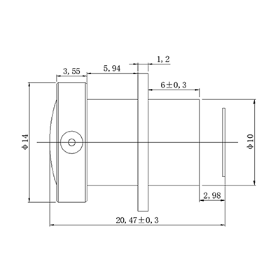
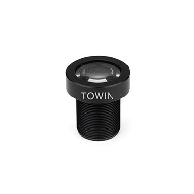
| M12 / S-Mount Lens | Compact size, embedded vision, sensor coverage, and required image detail | M12 Lenses |
| C-Mount Lens | Industrial camera compatibility, sensor format, focal length, and optical resolution | C-Mount Lenses |
| CS-Mount Lens | Camera interface, installation geometry, focal length, and application requirements | CS-Mount Lenses |
| Low-Distortion Lens | Geometric accuracy, dimensional measurement, and calibration requirements | Low-Distortion Lenses |
| High-Resolution Industrial Lens | Sensor coverage, fine-detail reproduction, MTF, and edge performance | 1.1-Inch 20MP Machine Vision Lenses |
M12, C-Mount, and CS-Mount describe different lens interfaces or mechanical formats, while low distortion and high resolution describe optical characteristics. These categories are not mutually exclusive. A suitable lens must meet both the camera’s mechanical requirements and the application’s optical requirements.
Browse the full TOWIN industrial lens product range to compare available categories and identify potential candidates.
5. Practical Example: Selecting a Lens for Surface Inspection
Consider a machine vision system designed to inspect metal components for surface scratches.
| Requirement | Example | Selection Consideration |
|---|---|---|
| Target size | 100 × 80 mm | Choose an FOV that covers the component and required positioning margin. |
| Smallest defect | 0.2 mm | Verify that the lens and sensor can reproduce the defect with sufficient contrast. |
| Working distance | Limited by the machine layout | Estimate focal length using the available distance and required FOV. |
| Main objective | Surface-defect detection | Prioritize detail visibility, focus, and suitable illumination. |
The first step is to define the required coverage and determine how the smallest defect will appear on the sensor. Next, use the camera specifications and available working distance to estimate the focal length.
The candidate lens must then be evaluated for resolution, image-circle coverage, distortion, and depth of field. Because metal surfaces may be reflective, lighting also plays an important role. Diffuse, directional, or low-angle illumination may reveal different types of surface defects.
This example illustrates why machine vision lens selection cannot be based on a single specification. The final configuration must be evaluated as a complete imaging system using representative samples and realistic operating conditions.
6. Common Mistakes in Machine Vision Lens Selection
Choosing a Lens Based Only on Megapixels
A high megapixel rating does not guarantee adequate image detail. Check optical resolution, MTF, pixel pitch, contrast, and performance across the required field.
Ignoring the Smallest Feature
A lens may capture the entire object but still fail to reveal small defects. Define the smallest feature that must be detected before selecting the optical system.
Considering FOV Without Working Distance
FOV and working distance must be evaluated together. A lens configuration that works at one distance may not provide the required coverage when installation conditions change.
Overlooking Distortion in Measurement Applications
Geometric distortion can affect dimensional measurement and positioning. Establish the required accuracy and evaluate the complete calibration process before selecting a lens.
Skipping Practical Testing
Lens specifications alone cannot guarantee inspection performance. Validate the selected lens with the actual camera, lighting, object, and image-processing workflow.
7. Frequently Asked Questions
Q1: How do I select the right lens for a machine vision camera?
A: Start with the inspection task, camera sensor, target dimensions, smallest feature, and working distance. Then evaluate FOV, focal length, optical resolution, distortion, aperture, depth of field, and mechanical compatibility. Test the final configuration under real operating conditions.
Q2: How do I match a lens to my camera sensor?
A: Check that the lens image circle covers the sensor and that the mount is compatible. Also consider pixel pitch, sensor resolution, and lens resolving power. A suitable match should provide the required image detail across the area used for inspection.
Q3: How do I calculate the focal length for machine vision?
A: Focal length depends on the sensor format, required field of view, and working distance. Use these values to estimate a starting focal length, then confirm that the selected lens supports the required coverage and image quality. A calculator can provide an estimate, but actual lens specifications must be verified.
Q4: Does a higher-megapixel lens always provide better image quality?
A: No. Image quality depends on the complete optical system, including lens MTF, pixel pitch, contrast, aperture, illumination, and focus. A higher nominal megapixel rating alone does not guarantee that small defects will be visible.
Q5: When should I use a low-distortion lens?
A: Consider a low-distortion lens for dimensional measurement, precision positioning, and geometric analysis when image deformation could affect the required accuracy. The necessary distortion performance depends on the application’s error budget and calibration method.
Q6: What is the difference between M12, C-Mount, and CS-Mount lenses?
A: These lens types use different mechanical interfaces and are suited to different camera designs and integration requirements. The correct choice depends on the camera mount, sensor coverage, available space, focal length, and required optical performance. Always verify mechanical and optical compatibility before ordering.
Q7: Can TOWIN help select a lens for a custom machine vision project?
A: You can share your camera specifications, sensor size, field of view, working distance, inspection target, and required image quality with TOWIN. These details help establish the project requirements and determine which standard or customized lens options may be suitable.
8. Conclusion: Build a Reliable Machine Vision Imaging System
Successful Machine Vision Camera Lens Selection begins with a clear understanding of the inspection task and the camera’s specifications. Sensor size, field of view, working distance, focal length, optical resolution, distortion, and depth of field must work together to produce the required image quality.
Start by defining the smallest feature to detect and the area that must be captured. Use the FOV Calculator and Focal Length Calculator to estimate the initial configuration, then compare suitable M12 lenses, C-Mount lenses, and other options in the TOWIN product range.
Before finalizing a lens, validate its performance with the intended camera, lighting, target, and inspection process. If your application has demanding optical, mechanical, or environmental requirements, contact TOWIN to discuss a suitable industrial lens solution.