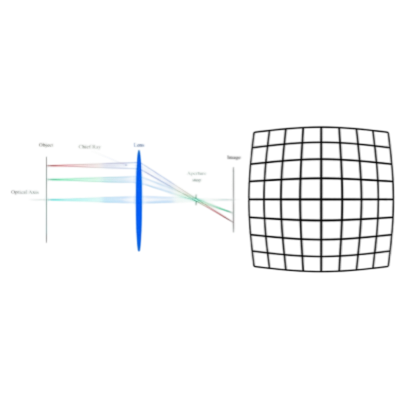


Optical Design for Industrial Vision Systems
Knowledge Center
Lorem ipsum dolor sit amet, consectetur adipiscing elit, sed do eiusmod tempor incididunt ut labore et dolore magna aliqua. Ut enim ad minim veniam, quis nostrud exercitation ullamco laboris nisi ut aliquip ex ea commodo consequat. Duis aute irure dolor in reprehenderit in voluptate velit esse cillum dolore eu fugiat nulla pariatur. Excepteur sint occaecat cupidatat non proident, sunt in culpa qui officia deserunt mollit anim id est laborum.
What Is Optical Design?
Requirements

Define application needs and key performance parameters.
Optical Design
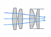
Create initial lens architecture and optical specifications.
Simulation
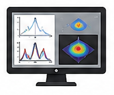
Use optical software to simulate imaging performance.
Optimization

Optimize lens structure and parameters to meet targets.
Prototype
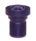
Build and assemble prototypes for real-world evaluation.
Testing
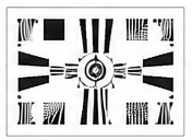
Test optical performance (MTF, distortion, RI, etc.) and validate.
Mass Production
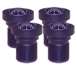
Finalize design and scale up to stable mass production.
The goal of optical design is to achieve the best balance of resolution, distortion, field of view, depth of field, relative illumination, and mechanical constraints for a given application.
Why It Matters
Higher Imaging Quality
Sharper images with better contrast and detail.
Lower System Cost
Optimized designs reduce tolerance, assembly, and rework costs.
Compact & Lightweight
Advanced optical design enables smaller, lighter lens systems.
Reliable Performance
Robust designs ensure consistent performance in real-world conditions.
Faster Time to Market
Efficient design and validation process shortens development cycle.
Why Optical Design Matters in Industrial Imaging
In industrial imaging, optical performance determines the quality of every image before software processing begins. Image sensors, AI algorithms, and vision software can only analyze the information captured by the lens—they cannot recover details that were never recorded.
A well-optimized optical design maximizes image quality by balancing resolution, distortion, MTF, relative illumination, and sensor compatibility. This ensures reliable inspection, accurate measurement, and consistent performance in demanding industrial environments.
Whether the application is machine vision, robotics, medical imaging, smart traffic, or autonomous navigation, optimized optics reduce system errors and improve long-term operational stability.
The Optical Imaging Performance Chain

Object
Real-world scene or target

Lens Design
Controls light and forms the image
Image Sensor
Captures optical information

AI / Software
Processes and analyzes the data
Result / Decision
Drives accurate decisions & actions
Optical Design Factor Impact Matrix
| Optical Design Factor | Influence on Imaging Performance | Why It Matters | Typical Applications |
|---|---|---|---|
| Resolution | Image Detail | Determines the ability to capture fine details and small features. | PCB Inspection, Surface Inspection, Micro-level Measurement |
| Distortion | Measurement Accuracy | Low distortion ensures accurate size measurement and reduces geometric error. | Metrology, 3D Measurement, Precision Inspection |
| MTF | Edge Sharpness | Higher MTF provides better edge definition and improves recognition accuracy. | OCR, Barcode Reading, Object Recognition |
| Lens Coating | Light Transmission | High transmission and low reflection improve contrast and reduce flare and ghosting. | Smart Security, Traffic Monitoring, Low-Light Imaging |
| Aperture | Low-Light Performance | Larger aperture allows more light, improving performance in low-light conditions. | ITS, Surveillance, Robotics, DMS (Driver Monitoring) |
| Sensor Matching | Image Uniformity | Proper matching eliminates vignetting and ensures full sensor utilization. | Machine Vision, Industrial Cameras, High-Resolution Imaging |
| Focal Length | Field of View & Magnification | Determines the observable area and magnification level of the system. | Robotics, Drones, Intelligent Transport, Automated Inspection |
| Optical Materials | Color Accuracy | High-quality materials reduce chromatic aberration and improve color fidelity. | Medical Imaging, Life Science, Precision Measurement |
Engineering Insight
Optical design is the only stage that determines the quality of the optical information before it reaches the image sensor. Once image information is lost because of blur, distortion, or insufficient contrast, no software algorithm can fully restore it.
Key Benefits of Optimized Optical Design
Higher Measurement Accuracy
Achieve precise and repeatable results.
Better AI Recognition
High-quality data improves algorithm performance.
Lower Inspection Errors
Reduce false alarms and missing detections.
Improved System Reliability
Consistent performance in demanding conditions.
Design Trade-offs: Finding the Right Balance

Higher Resolution
Trade-off
More Cost
Smaller Pixel Size
Lower Light Sensitivity
Lower Distortion
Trade-off
Smaller FOV
More Complex Design
Higher Cost

Larger Aperture
Trade-off
Shallower DOF
More Lens Aberrations
Bigger Size

Wider FOV
Trade-off
More Distortion
Lower Edge Sharpness
More Complex Design

Longer Working Distance
Trade-off
Larger System Size
Lower Light Efficiency
Higher Cost
Design Principle
Successful optical design is not about maximizing a single parameter—it is about balancing resolution, distortion, field of view, depth of field, sensor compatibility, and manufacturability to achieve the best overall imaging performance for your specific application.
Key Parameters in Optical Design
Resolution
Why It Matters:
Determines the ability to capture fine details. Higher resolution enables more accurate inspection and measurement.
Distortion
Why It Matters:
Affects measurement accuracy and image geometry. Low distortion ensures reliable machine vision results.
Field of View (FOV)
Why It Matters:
Defines the observable area in the scene. The right FOV ensures the target is fully captured with optimal efficiency.
Working Distance (WD)
Why It Matters:
Determines the distance between the lens and object. Critical for system integration and ensuring operational flexibility.
Depth of Field (DOF)
Why It Matters:
Affects the range that remains in acceptable focus. Larger DOF improves tolerance to object height variations.
Relative Illumination
Why It Matters:
Ensures brightness uniformity across the image. High RI improves edge-to-edge consistency and inspection reliability.
Chief Ray Angle (CRA)
Why It Matters:
Large CRA can reduce image quality and cause shading. Lower CRA ensures better compatibility with sensors and microlenses.
Telecentricity
Why It Matters:
Telecentric design minimizes perspective error, which is essential for high-precision measurement applications.
Sensor Size
Why It Matters:
Must be matched with the image circle to avoid vignetting and ensure full sensor coverage.
Wavelength / Coating
AR Coating
Why It Matters:
Proper wavelength and coating selection improves transmission and reduces reflection for target applications.
Design Tip: There is always a trade-off between these parameters. The goal of optical design is to find the best balance based on your specific application requirements.
Optical Performance Curves
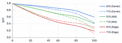
MTF Curve
Higher MTF values indicate better image sharpness and contrast.
MTF vs Spatial Frequency
Spatial Frequency (lp/mm)
Relative Illumination Curve
Shows the illumination uniformity across the image circle.
Relative Illumination vs Image Height
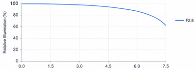
Image Height (mm)
Distortion Curve
Shows the percentage of distortion across the image height.
Distortion vs Image Height
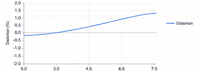
Image Height (mm)
CRA Distribution
Shows the Chief Ray Angle across the image circle.
CRA vs Image Height
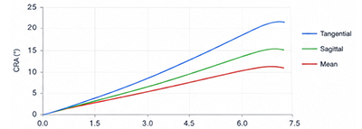
Image Height (mm)
Performance Summary
This lens provides high center resolution, good illumination uniformity, low distortion, and controlled CRA, making it ideal for machine vision, industrial inspection, and imaging applications.
Common Optical Aberrations
(No Aberration)
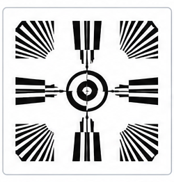
Sharp, high-contrast image
across the entire field.
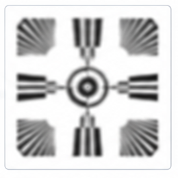
Image appears soft and hazy,
especially toward the edges.
1. Spherical Aberration
Occurs when light rays passing through the outer zones of a lens focus at a different point than rays passing through the center. This causes blurring and reduces image sharpness.
- ✓ Reduces contrast and sharpness
- ✓ Degrades performance wide open (low f-number)
- ✓ More noticeable in fast lenses and wide FOV systems
- ✓ Optimize lens element curvatures and spacing
- ✓ Use aspherical lens elements
- ✓ Stop down the aperture (increase F-number)
- ✓ Use advanced optical design software for optimization
(No Aberration)

Points are symmetric
and sharp across the field.
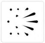
Points become comet-shaped,
worse toward the edge.
2. Coma
Occurs when off-axis light rays are focused asymmetric about the optical axis, causing point sources to appear as comet-like shapes.
- ✓ Degrades image quality off-axis
- ✓ Reduces sharpness toward the edges
- ✓ Common in fast, wide-angle lenses
- ✓ Optimize lens element shapes and spacing
- ✓ Use aspheric elements
- ✓ Balance the system in optical design
(No Aberration)
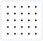
Points are sharp and
uniform in all directions.
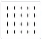
Points focus at different
lines, causing blur.
3. Astigmatism
Occurs when the lens has different focusing power in the tangential and sagittal planes.
- ✓ Causes directional blur
- ✓ Reduces resolution and contrast
- ✓ Affects measurement accuracy
- ✓ Correct with cylindrical elements
- ✓ Optimize lens symmetry
- ✓ Use advanced optical design software
(No Aberration)
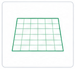
Image plane is flat,
objects at the edge are sharp.
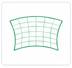
Image plane is curved,
edges may be out of focus.
4. Field Curvature
Occurs when the best focus position forms a curved surface instead of a flat plane.
- ✓ Edges may be out of focus
- ✓ Reduces sharpness across the field
- ✓ Affects large sensors and wide FOV
- ✓ Optimize lens design for flatter field
- ✓ Use field flattener elements
- ✓ Adjust working distance
(No Aberration)
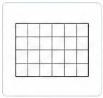
Straight lines remain
straight and undistorted.
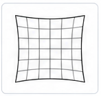
Lines bend (barrel or pincushion distortion).
5. Distortion
Occurs when magnification changes across the field, causing straight lines to appear curved.
- ✓ Impacts measurement accuracy
- ✓ Affects image geometry
- ✓ Important in machine vision and metrology
- ✓ Design lenses with low distortion
- ✓ Use symmetrical optical structures
- ✓ Calibrate in software if necessary
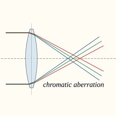
(No Aberration)
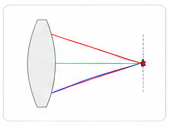
All colors focus at the same point.
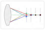
Different colors focus at different points.
6. Chromatic Aberration
Occurs because different wavelengths of light have different refractive indices and focus at different points.
- ✓ Causes color fringing (especially at high contrast edges)
- ✓ Reduces image clarity and contrast
- ✓ More visible in high-magnification and wide-aperture systems
- ✓ Use achromatic or apochromatic lens designs
- ✓ Select appropriate glass materials
- ✓ Use narrowband filters or coatings
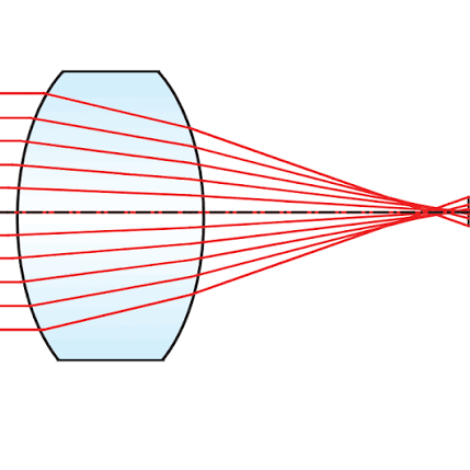
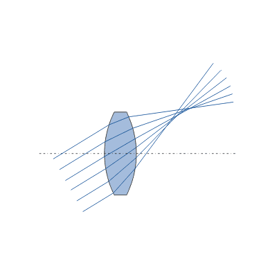
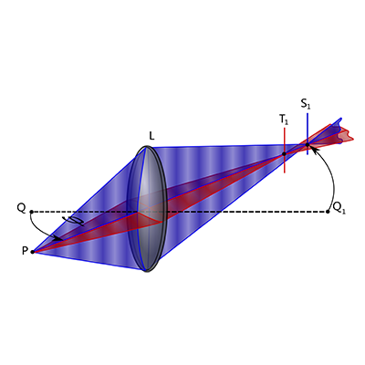
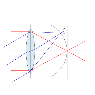

Why It Matters: Controlling aberrations is essential for achieving the resolution, contrast, and accuracy required in machine vision, metrology, robotics, and other high-performance imaging applications.
Optical Design for Machine Vision Applications
| Application | Key Requirement | Typical Resolution | Lens Type | Key Optical Considerations |
|---|---|---|---|---|
| PCB Inspection | Low Distortion | 5MP – 20MP | Low Distortion Lens | Minimize distortion < 1%, high center resolution, uniform illumination |
| Robot Vision | Wide FOV | 2MP – 12MP | Wide Angle Lens | Large FOV up to 120°+, low CRA, compact design |
| Barcode / OCR | DOF | 1MP – 5MP | Standard Lens | Adequate depth of field, high contrast, short working distance |
| Metrology | Telecentric | 5MP – 24MP | Telecentric Lens | Telecentricity, low distortion, high measurement accuracy |
| DMS (Driver Monitoring) | IR Corrected | 2MP – 8MP | IR Corrected Lens | IR wavelength support (850nm/940nm), high transmittance, low flare |
| ITS (Intelligent Transport) | Low CRA | 2MP – 12MP | Varifocal / Fixed Lens | Low chief ray angle, high resolution, weather resistance |
Why It Matters
- ✅Ensures accurate inspection and measurement
- ✅Improves system reliability and stability
- ✅Optimizes image quality and processing efficiency
- ✅Supports diverse industrial environments
💡Design Insight
Selecting the right optical design is critical for achieving the best balance between resolution, distortion, FOV, and depth of field based on your specific application.
Optical Design Applications
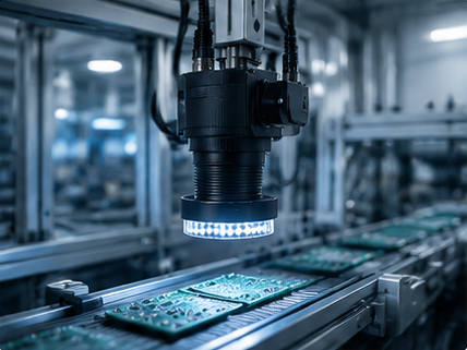
Machine Vision
Typical Requirements
< 1% Distortion
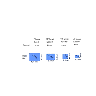
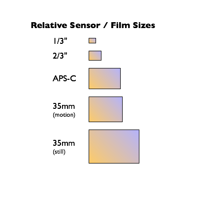
1/1.8" – 1/2.3"
C Mount / M12
High Resolution

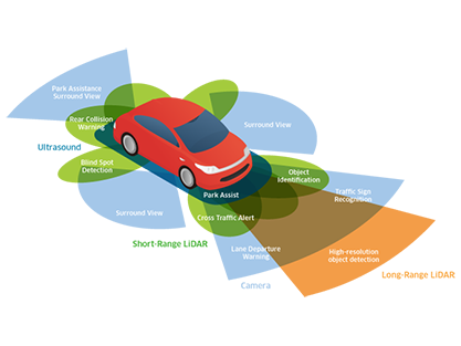
ADAS / DMS
Typical Requirements
2 – 8MP
Low Distortion
Wide FOV
High Transmittance
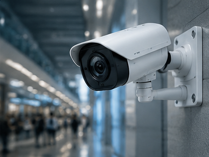
Smart Security
Typical Requirements
Low Light Performance
IR Corrected
Varifocal / Fixed
Weather Resistant
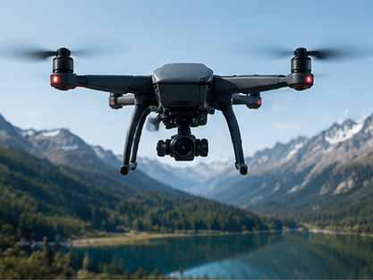
Drone Imaging
Typical Requirements
Wide FOV
High Resolution
Low Distortion
Vibration Resistant
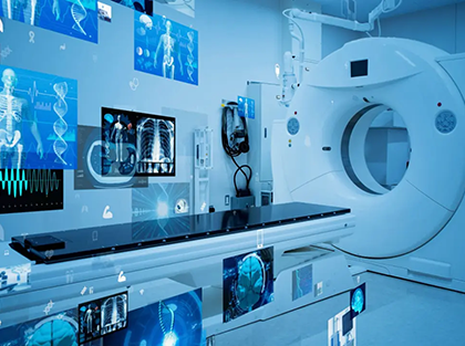
Medical Imaging
Typical Requirements
Low Distortion
Telecentric Options
Color Accuracy
High Reliability

Biometric Recognition
Typical Requirements
2 – 8MP
Low Distortion
Compact Size
High Accuracy
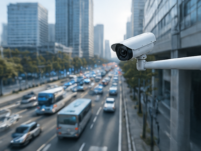
Smart Traffic (ITS)
Typical Requirements
2 – 12MP
Varifocal Options
Weather Resistant
High Reliability
Industrial Lens Optimization Process
Industrial optical design involves iterative optimization between imaging requirements, sensor characteristics, and manufacturing limitations.
Optical engineers use advanced simulation software to refine lens performance and ensure consistency across production batches.
Featured Optical Articles
More Optical Design Topics
.png)
Frequently Asked Questions
Need Custom Optical Lens Design Support?
Towin provides industrial optical solutions for machine vision, robotics, smart traffic, medical imaging, and AI vision applications.
Let’s Build the Right Optical Solution Together
Have a question, need a quote, or want to discuss your project? Our optical experts are ready to help.

Expert Support
Get professional advice from our optical engineers.

Tailored Solutions
We provide customized lens solutions that fit your application.

Reliable Quality
High-quality manufacturing with strict testing and quality control.

Fast Response
We value your time and will get back to you as soon as possible.
Send Us a Message