


Global Shutter vs Rolling Shutter: Which One Is Better
07/01/2026
Machine Vision Camera Sensor Formats Explained
07/03/2026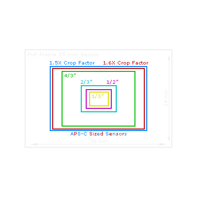
How to Match a Lens to Your Sensor is one of the most important steps when designing an industrial imaging system. Selecting a high-quality camera or an advanced image sensor alone does not guarantee excellent image quality. The lens and sensor must work together as a complete optical system to deliver sharp images, accurate measurements, and reliable machine vision performance.
A mismatch between the lens and the sensor can lead to vignetting, reduced edge sharpness, poor resolution, distorted images, or unnecessary hardware costs. Whether you are building a machine vision inspection system, an autonomous robot, a smart traffic camera, or a medical imaging device, understanding lens-to-sensor compatibility is essential for achieving the best optical performance.
This guide explains how to match a lens to your sensor step by step. You’ll learn how sensor size, image circle, pixel size, resolution, focal length, lens mount, and field of view work together during lens selection. If you’re new to industrial imaging, we also recommend starting with our Image Sensor Guide, which provides a complete introduction to sensor specifications before selecting a lens.
Why Lens and Sensor Matching Matters
Many engineers focus primarily on sensor resolution or lens focal length, but the overall imaging performance depends on how well both components are matched. Even the highest-resolution sensor cannot produce clear images if the lens cannot resolve sufficient detail, while an excellent lens cannot compensate for an improperly selected sensor.
Correct lens and sensor matching provides several important benefits:
- Maximum image sharpness across the entire frame
- Full sensor coverage without dark corners (vignetting)
- Higher measurement accuracy for machine vision inspection
- Better low-light performance through optimized optical efficiency
- Reduced optical distortion and edge blur
- Improved reliability for AI image recognition and automated inspection
In industrial applications such as Machine Vision, Robotics Vision, Smart Traffic, and Medical Imaging, proper lens matching directly affects inspection accuracy, object detection, barcode reading, robotic guidance, and dimensional measurement.
Engineer Tip
Think of the sensor as the receiver and the lens as the information provider. If either component limits performance, the entire imaging system is limited.
Step 1 – Understand Your Sensor Specifications
Before selecting any industrial lens, you should first understand the specifications of your image sensor. These parameters determine which lenses are physically compatible and whether the optical performance will meet your application’s requirements.
| Sensor Specification | Why It Matters |
|---|---|
| Sensor Format | Determines the minimum image circle required from the lens. |
| Sensor Size | Influences field of view and lens coverage. |
| Resolution | Determines the resolving power required from the lens. |
| Pixel Size | Affects image sharpness, sensitivity, and lens MTF requirements. |
| Aspect Ratio | Impacts field of view calculations. |
| Shutter Type | Determines suitability for moving objects. |
If you’re unfamiliar with these specifications, our Sensor Guide explains each parameter in detail, including sensor formats, pixel size, global shutter, rolling shutter, and sensor resolution.
Sensor Size Is the Starting Point
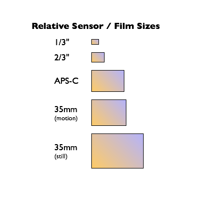
Among all sensor parameters, sensor size is usually the first factor to consider. It determines how much of the image projected by the lens will actually reach the sensor.
Typical industrial sensor formats include:
- 1/4″
- 1/3″
- 1/2.8″
- 1/2″
- 2/3″
- 1″
- 1.1″
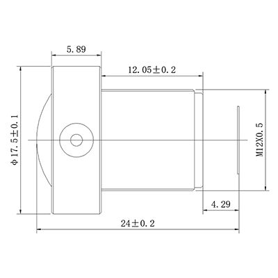
Larger sensors generally require lenses with larger image circles, while smaller sensors are compatible with more compact optical designs such as many M12 lenses.
Resolution Determines Lens Performance Requirements
Higher sensor resolution captures more image detail, but it also demands higher optical performance from the lens. For example, an 8MP sensor paired with a low-resolution lens may produce blurry images because the lens cannot resolve enough detail to fully utilize the sensor.
When selecting a lens, always evaluate both the sensor resolution and the optical resolving capability of the lens instead of considering either component independently.
Step 2 – Match the Lens Image Circle
Once the sensor specifications are understood, the next step is ensuring that the lens provides a sufficiently large image circle. Image circle refers to the circular image projected by the lens onto the sensor surface.
The image circle must always be equal to or larger than the sensor’s diagonal dimension. If the projected image is too small, the sensor cannot be fully illuminated, resulting in dark corners, reduced usable image area, and lower inspection accuracy.
Correct Image Circle Matching
- ✓ Image circle completely covers the sensor
- ✓ Full field of view is available
- ✓ Uniform illumination across the image
- ✓ No corner shading
Incorrect Image Circle Matching
- ✗ Black corners (vignetting)
- ✗ Reduced effective field of view
- ✗ Lower image quality near the edges
- ✗ Reduced measurement accuracy
Many compact embedded vision systems use M12 lenses designed for 1/3″, 1/2.8″, or 1/2″ sensors, while larger industrial cameras often require FA lenses or C-mount lenses capable of covering 1-inch or larger sensors.
Besides image circle, engineers should also consider the required Field of View (FOV), working distance, and application environment before finalizing the lens selection.
Best Practice
Always choose a lens with an image circle that fully covers your sensor. A larger image circle is generally acceptable, but a smaller image circle will almost always reduce usable image quality.
Step 3 – Match Lens Resolution to Sensor Resolution
At this stage of How to Match a Lens to Your Sensor, many engineers make the mistake of focusing only on the camera sensor’s megapixel rating. In reality, image quality depends on both the sensor and the lens. A high-resolution sensor paired with a low-resolution lens cannot deliver its full performance because the lens becomes the limiting factor.
The lens must provide sufficient optical resolving power to reproduce the fine details captured by the sensor. This capability is often described by the lens’s Modulation Transfer Function (MTF), which measures how well the lens preserves image contrast at different spatial frequencies.
If the lens resolution is lower than the sensor resolution, the resulting image may appear soft, even when using an expensive high-megapixel camera. For a deeper understanding of optical performance, see our Optical Design Guide.
Typical Resolution Matching Guide
| Sensor Resolution | Recommended Lens | Typical Applications |
|---|---|---|
| 2 MP | Standard M12 Lens | General Machine Vision, Barcode Reading |
| 5 MP | High-Resolution M12 Lens | Robot Guidance, AI Cameras |
| 8 MP | Premium M12 Lens / FA Lens | Precision Inspection, PCB AOI |
| 12 MP | Industrial FA Lens | Measurement Systems |
| 20 MP and Above | High-End FA Lens | Semiconductor Inspection, Metrology |
Recommended Resolution Workflow
1920 × 1080
↓
2 MP Sensor
↓
Typical M12 Lens
↓
General Machine Vision
3840 × 2160
↓
8 MP Sensor
↓
High-Resolution Lens
↓
Precision Inspection
5120 × 3840
↓
20 MP Sensor
↓
Industrial FA Lens
↓
Metrology & Semiconductor Inspection
Engineer Tip
Higher resolution does not automatically mean better image quality. If lighting conditions are limited, increasing resolution while reducing pixel size may introduce more image noise. Always evaluate sensor resolution together with lens resolving power and application requirements.
Step 4 – Consider Pixel Size
Pixel size is another critical factor when learning How to Match a Lens to Your Sensor. Pixel size determines how much light each pixel can collect, directly affecting image sensitivity, signal-to-noise ratio (SNR), and low-light performance.
Although modern image sensors continue to increase resolution, this is often achieved by reducing the size of individual pixels. Smaller pixels can capture finer image details under ideal lighting conditions, but they also collect less light, making the imaging system more sensitive to noise.
Larger pixels generally provide better dynamic range and higher image quality in challenging lighting environments. For industrial inspection systems operating under variable illumination, balancing pixel size and sensor resolution is often more important than simply choosing the highest megapixel sensor.
Small Pixels vs Large Pixels
| Small Pixels | Large Pixels |
|---|---|
| Higher Resolution | Higher Light Sensitivity |
| Capture More Detail | Better Signal-to-Noise Ratio |
| Lower Light Collection | Improved Low-Light Performance |
| Higher Image Noise | Lower Image Noise |
| Require Higher Lens MTF | Less Demanding on Lens Resolution |
For more information about pixel size, sensor sensitivity, and image quality, refer to our Sensor Guide.
Step 5 – Select the Correct Lens Mount
Even if the optical specifications are perfectly matched, the lens must also be mechanically compatible with the camera. Choosing the correct lens mount ensures proper flange distance, stable installation, and reliable optical alignment.
The three most common lens mounts used in industrial imaging are M12, C Mount, and CS Mount.
| Lens Mount | Typical Sensor Size | Typical Applications |
|---|---|---|
| M12 | 1/4″ – 1/2″ | Embedded Vision, Robotics, AI Cameras |
| C Mount | Up to 1″ | Machine Vision, Industrial Inspection |
| CS Mount | Security Cameras | Video Surveillance |
For compact imaging systems, our M12 Lens Series offers a wide selection of focal lengths and sensor compatibility options. Larger industrial inspection systems often require FA lenses or C-mount optics for higher image quality and larger sensor coverage.
Step 6 – Verify the Required Field of View
The final step is verifying that the selected sensor and lens combination provides the required field of view (FOV). Even when the lens is mechanically compatible and offers sufficient resolution, the imaging system may still fail if the field of view is too narrow or unnecessarily wide.
Field of view depends on three primary factors:
- Sensor Size
- Lens Focal Length
- Working Distance
These parameters should always be evaluated together during lens selection.
To simplify this process, use the Interactive FOV Calculator, which instantly estimates the horizontal and vertical field of view based on your sensor dimensions, focal length, and working distance.
Application Requirements
↓
Select Sensor
↓
Choose Lens
↓
Calculate Field of View
↓
Verify Image Coverage
↓
Prototype & Test
Lens Selection Examples
The following examples demonstrate how engineers typically match lenses with different image sensors across various industrial applications.
| Application | Sensor | Recommended Lens |
|---|---|---|
| Barcode Reading | 1/3″ CMOS | 4 mm M12 Lens |
| PCB Inspection | 1/2″ 5 MP Sensor | 8 mm High-Resolution M12 Lens |
| Robot Guidance | 2/3″ Sensor | Industrial FA Lens |
| Medical Imaging | 1″ CMOS Sensor | Low Distortion FA Lens |
| Traffic Monitoring | 1″ Global Shutter Sensor | Telephoto Industrial Lens |
The best lens always depends on your application’s accuracy requirements, sensor specifications, working distance, lighting conditions, and installation constraints. Engineers should evaluate the complete optical system rather than selecting components independently.
Common Lens and Sensor Matching Mistakes
Even experienced engineers can encounter imaging issues when selecting industrial lenses. In many cases, poor image quality is not caused by a defective camera or lens, but by an incorrect combination of optical components. Understanding these common mistakes can help improve system performance and reduce development time.
1. Choosing a Lens Based Only on Focal Length
Many users select a lens simply because it provides the desired field of view. However, focal length is only one part of the selection process. Sensor size, image circle, lens resolution, distortion, and working distance must also be considered.
2. Ignoring Image Circle Compatibility
A lens with an image circle smaller than the sensor will produce dark corners (vignetting) and reduce the usable imaging area. Always ensure the lens image circle fully covers the sensor.
3. Using a Low-Resolution Lens with a High-Resolution Sensor
Pairing an 8 MP or 20 MP sensor with a standard low-resolution lens prevents the sensor from reaching its full potential. Match the optical resolving power of the lens to the sensor resolution.
4. Overlooking Pixel Size
Smaller pixels require better lens performance and sufficient illumination. Choosing the highest-resolution sensor without considering pixel size often increases image noise in low-light environments.
5. Selecting the Wrong Lens Mount
Mechanical compatibility is just as important as optical compatibility. Verify the lens mount, flange focal distance, and camera interface before purchasing a lens.
6. Skipping Field of View Verification
Always calculate the field of view before ordering a lens. A simple FOV calculation can prevent costly redesigns and ensure the selected lens captures the required inspection area.
Use our Interactive FOV Calculator to verify your imaging coverage before finalizing your design.
Frequently Asked Questions
1. How do I know if a lens is compatible with my sensor?
Check the sensor size, image circle, lens resolution, lens mount, and required field of view. A compatible lens should fully cover the sensor while providing sufficient optical resolution for the application.
2. Can one industrial lens support multiple sensor sizes?
Yes. If the lens provides an image circle larger than all target sensors, it can usually be used with multiple sensor formats. However, the effective field of view will change depending on the sensor size.
3. What happens if the image circle is smaller than the sensor?
The sensor will not be fully illuminated, resulting in dark corners, reduced image quality, and lower measurement accuracy.
4. Does higher sensor resolution always require a better lens?
Generally, yes. Higher-resolution sensors require lenses with higher resolving power and better MTF performance to fully utilize the available image detail.
5. Should I choose an M12 lens or a C-mount lens?
M12 lenses are ideal for compact embedded vision systems and small sensors, while C-mount lenses are commonly used with larger sensors and high-precision industrial inspection systems.
6. How does sensor size affect field of view?
Larger sensors capture a wider field of view when used with the same focal length. Sensor size should always be considered together with focal length and working distance.
7. Can software correct poor lens and sensor matching?
Image processing can compensate for certain optical issues such as distortion, but it cannot recover image detail that the lens fails to capture. Proper optical design is always the preferred solution.
8. What is the easiest way to verify my lens selection?
Calculate the required field of view, verify image circle compatibility, compare sensor resolution with lens resolution, and test the complete imaging system under actual operating conditions.
Related Resources
To further improve your understanding of industrial imaging systems, explore these related resources:
- Image Sensor Guide
- Optical Design for Industrial Vision Systems
- Industrial Lens Selection Guide
- Interactive FOV Calculator
- Lens Distortion Guide
- Lens Basics
If you are designing systems for specific industries, you may also find these solution pages helpful:
Need Help Matching Your Lens and Sensor?
Choosing the right optical components can significantly improve image quality, inspection accuracy, and system reliability. Whether you’re developing a compact embedded vision camera or a high-resolution industrial inspection system, our optical engineers can help you select the most suitable lens for your image sensor and application.
- ✔ Sensor and Lens Compatibility Analysis
- ✔ Field of View Optimization
- ✔ M12 Lens Recommendations
- ✔ FA Lens Selection Support
- ✔ Custom Optical Design
- ✔ OEM & ODM Manufacturing
Contact Our Engineering Team to discuss your project requirements or Request a Quote for personalized lens recommendations.
Conclusion
How to Match a Lens to Your Sensor is more than simply selecting a compatible lens mount or focal length. A successful imaging system requires careful consideration of sensor size, image circle, resolution, pixel size, field of view, and optical performance. When these factors are evaluated together, engineers can maximize image quality, improve measurement accuracy, and reduce system development risks.
Whether your application involves machine vision, robotics, intelligent transportation, medical imaging, or embedded AI cameras, investing time in proper lens and sensor matching will produce better long-term results. By combining the guidance in this article with our Sensor Guide, FOV Calculator, and Industrial Lens Selection Guide, you can confidently select the optimal optical solution for your next project.