


Machine Vision Camera Sensor Formats Explained
07/03/2026
Low Distortion Lenses for Precision Measurement
07/05/2026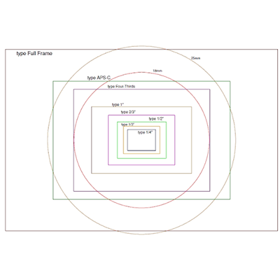
Image Circle is one of the most important—but often overlooked—factors when selecting an industrial lens. Many imaging issues, including dark corners, vignetting, cropped images, and reduced measurement accuracy, are caused not by poor lens quality but by an Imaging Circle that does not properly match the camera sensor.
Whether you are designing a machine vision system, building a robotics camera, integrating a smart traffic solution, or developing medical imaging equipment, understanding how Image Circle works will help you choose compatible lenses, maximize image quality, and avoid costly design mistakes.
In this guide, you’ll learn what an Imaging Circle is, why it matters, how it relates to sensor size, and how to select the correct lens for your application. If you’re new to industrial image sensors, we also recommend reading our complete Image Sensor Guide before selecting a lens.
What Is Image Circle?
An Image Circle is the circular area of usable light projected by a lens onto the image sensor. Every optical lens produces a circular image, while the camera sensor captures only the portion of that image that falls within its rectangular active area.
For optimal imaging performance, the diameter of the Imaging Circle should be equal to or larger than the diagonal size of the image sensor. If the Imaging Circle is too small, parts of the sensor will not receive enough light, resulting in dark corners or cropped images.
Unlike focal length, which determines the field of view, or aperture, which controls the amount of light entering the lens, the Imaging Circle determines whether the lens can fully cover the camera sensor.
If you’re unfamiliar with other optical fundamentals, our Lens Basics Guide explains the relationship between focal length, aperture, sensor size, and other important lens parameters.
Why Image Circle Matters
Selecting the correct Image Circle is essential for achieving reliable imaging performance. Even a high-resolution industrial lens cannot produce optimal results if its Image Circle is smaller than the camera sensor.
Proper Imaging Circle matching offers several important advantages:
- Complete Sensor Coverage – Ensures the entire sensor receives usable image information.
- Prevents Vignetting – Eliminates dark corners caused by insufficient optical coverage.
- Maintains Image Resolution – Allows the sensor to utilize the full optical performance of the lens.
- Improves Measurement Accuracy – Especially important for machine vision inspection and precision metrology.
- Simplifies Lens Selection – Helps engineers quickly identify compatible industrial lenses.
In industrial automation, improper Imaging Circle matching may lead to inspection errors, inaccurate dimensional measurements, reduced AI recognition accuracy, and inconsistent imaging performance.
Image Circle selection becomes even more critical when designing systems for high-resolution cameras, where every pixel contributes to measurement precision.
Image Circle vs. Sensor Size
The relationship between Image Circle and sensor size is straightforward:
The Image Circle should always be equal to or larger than the sensor’s diagonal dimension.
Many engineers mistakenly compare Imaging Circle with the sensor width. In reality, compatibility is determined by the sensor diagonal, since this is the longest distance across the sensor.
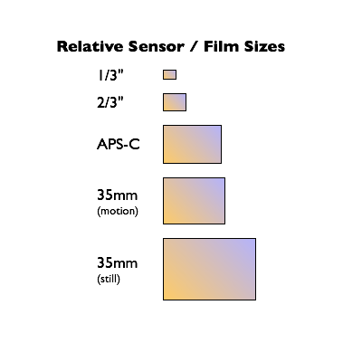
The following table shows typical industrial sensor sizes and their corresponding minimum Imaging Circle requirements.
| Sensor Format | Approx. Sensor Diagonal | Recommended Minimum Image Circle |
|---|---|---|
| 1/4″ | ≈4.0 mm | ≥4 mm |
| 1/3″ | ≈6.0 mm | ≥6 mm |
| 1/2.8″ | ≈6.5 mm | ≥6.5 mm |
| 1/2″ | ≈8.0 mm | ≥8 mm |
| 2/3″ | ≈11 mm | ≥11 mm |
| 1″ | ≈16 mm | ≥16 mm |
| 1.1″ | ≈17.6 mm | ≥18 mm |
Understanding sensor dimensions is the foundation of correct lens selection. If you’re unsure about common sensor formats, refer to our Sensor Size Guide, which explains sensor dimensions, pixel size, image formats, and compatibility in detail.
Once the Image Circle is confirmed, the next step is determining the correct field of view. Our Field of View Calculator helps calculate the required focal length based on your sensor size and working distance.
What Happens If the Imaging Circle Is Too Small?
Choosing a lens with an Imaging Circle that is smaller than the camera sensor is one of the most common mistakes in industrial imaging. While the lens may appear mechanically compatible, it cannot fully illuminate the sensor, resulting in degraded image quality and unreliable inspection performance.
When the Imaging Circle does not completely cover the sensor, the following problems may occur:
- Vignetting – Dark or black corners appear because the outer area of the sensor receives insufficient light.
- Reduced Effective Field of View – Portions of the sensor become unusable, decreasing the available imaging area.
- Lower Measurement Accuracy – Missing image data can reduce the precision of dimensional inspection and metrology applications.
- Uneven Brightness – Illumination gradually decreases toward the image edges, making image processing more difficult.
- Poor AI Recognition Performance – Machine learning and object detection algorithms rely on complete image information. Cropped or dark images may reduce detection accuracy.
For industrial machine vision systems, selecting a lens with adequate Imaging Circle coverage is essential for maintaining stable imaging performance and reliable inspection results.
How to Choose the Right Image Circle
Selecting the correct Image Circle is a straightforward process once the camera sensor specifications are known. Instead of selecting a lens based only on focal length, engineers should first verify that the lens can fully cover the sensor.
Step 1 — Identify Your Camera Sensor Size
Begin by determining the sensor format used in your camera, such as 1/3″, 1/2″, 2/3″, or 1″. Larger sensors require larger Image Circles.
If you are unsure about sensor formats, our Image Sensor Guide explains common industrial sensor sizes and their characteristics.
Step 2 — Check the Sensor Diagonal
The required Image Circle is determined by the sensor’s diagonal dimension—not its width or height.
As a general rule:
Recommended Image Circle ≥ Sensor Diagonal
Step 3 — Verify Lens Specifications
Industrial lens datasheets normally specify the maximum supported sensor size or Image Circle. Always confirm that the specified Image Circle is compatible with your camera sensor.
Step 4 — Calculate the Required Field of View
After confirming sensor compatibility, calculate the required Field of View (FOV) according to your working distance and inspection target.
Our Interactive FOV Calculator can help determine the appropriate focal length for your application.
Step 5 — Verify Other Lens Parameters
Image Circle is only one part of lens selection. Engineers should also evaluate:
- Focal Length
- Lens Resolution
- Distortion
- Aperture (F Number)
- Working Distance
- Mount Type
- Environmental Requirements
For a complete workflow, see our Machine Vision Lens Selection Guide.
Image Circle in Different Industrial Applications
Different industries use different sensor sizes and imaging requirements. As sensor size increases, larger Image Circles are typically required to maintain full sensor coverage.
| Application | Typical Sensor | Recommended Image Circle | Typical Lens |
|---|---|---|---|
| Machine Vision Inspection | 2/3″ | ≥11 mm | FA Lens / Low Distortion Lens |
| Robotics Vision | 1/2″ | ≥8 mm | M12 Lens |
| Medical Imaging | 1″ | ≥16 mm | High Resolution C-Mount Lens |
| Smart Traffic | 1″ | ≥16 mm | Long Focal Length C-Mount Lens |
| Smart Security | 1/2.8″ | ≥6.5 mm | M12 Lens |
| Drone Imaging | 1/2.3″ | ≥8 mm | Lightweight M12 Lens |
Choosing the correct Image Circle helps ensure that the sensor operates at its full potential across different industrial imaging applications.
Learn more about complete imaging solutions for Machine Vision, Robotics Vision, Medical Imaging, and Smart Traffic.
Common Mistakes When Choosing an Image Circle
Even experienced engineers occasionally misunderstand how Imaging Circle affects lens compatibility. Avoiding the following mistakes can significantly improve system performance.
❌ Mistake 1 — Only Considering Focal Length
Focal length determines the field of view, but it does not indicate whether the lens can fully cover the camera sensor.
❌ Mistake 2 — Ignoring Sensor Size
Always verify the sensor format before selecting a lens. A mismatch between sensor size and Imaging Circle often causes vignetting.
❌ Mistake 3 — Confusing Mount Size with Imaging Circle
Lens mount standards such as M12 or C-Mount define mechanical compatibility only. They do not determine optical coverage.
❌ Mistake 4 — Assuming a Larger Imaging Circle Always Means Better Performance
A larger Imaging Circle provides greater sensor coverage, but choosing an oversized lens may increase cost, weight, and system size without improving image quality.
❌ Mistake 5 — Ignoring Lens Distortion and Resolution
Imaging Circle should always be evaluated together with distortion, resolution, MTF performance, and application requirements.
Understanding these common mistakes helps engineers build more reliable imaging systems while reducing development costs and system redesign.
To learn how optical design influences Imaging Circle, distortion, and imaging performance, read our Optical Design Guide.
How Image Circle Relates to Other Lens Parameters
Although Image Circle is a critical specification when selecting an industrial lens, it should never be evaluated in isolation. A high-performance imaging system depends on the correct combination of sensor size, focal length, resolution, distortion control, and optical design.
The table below summarizes how Image Circle interacts with other important optical parameters.
| Lens Parameter | Relationship to Image Circle | Selection Priority |
|---|---|---|
| Sensor Size | The Image Circle must completely cover the sensor diagonal. | ★★★★★ |
| Focal Length | Determines the Field of View but does not affect sensor coverage. | ★★★★★ |
| Field of View (FOV) | Calculated after confirming Image Circle compatibility. | ★★★★ |
| Lens Resolution | Higher-resolution sensors require lenses with matching optical performance. | ★★★★☆ |
| Lens Distortion | Does not affect Image Circle but directly impacts measurement accuracy. | ★★★★☆ |
| Lens Mount | Provides mechanical compatibility only and does not determine Image Circle. | ★★★☆☆ |
| Optical Design | Influences illumination uniformity, aberration correction, and overall image quality. | ★★★★★ |
Successful industrial imaging requires balancing all of these parameters together rather than optimizing a single specification.
To better understand these optical concepts, explore our Optical Design Guide, Lens Selection Guide, and Interactive FOV Calculator.
Recommended Lens Types by Image Circle
Different Image Circle sizes are typically associated with different industrial lens categories. Choosing the appropriate lens type helps ensure compatibility while meeting your application’s imaging requirements.
| Recommended Image Circle | Typical Sensor | Recommended Lens Type | Typical Applications |
|---|---|---|---|
| ≈6 mm | 1/3″ | M12 Lens | Smart Security, Embedded Vision |
| ≈8 mm | 1/2″ | M12 Lens | Robotics, AI Cameras |
| ≈11 mm | 2/3″ | Low Distortion Lens / FA Lens | Machine Vision Inspection |
| ≈16 mm | 1″ | C-Mount Lens | Medical Imaging, Smart Traffic |
| >20 mm | Large Format Sensors | FA Lens | Precision Measurement & Industrial Metrology |
In addition to Image Circle, engineers should evaluate distortion, resolution, focal length, working distance, and environmental conditions before selecting an industrial lens.
Frequently Asked Questions
1. What is an Imaging Circle?
An Imaging Circle is the circular area of light projected by a lens that contains usable image information. The Imaging Circle must completely cover the camera sensor to produce a full image.
2. How do I calculate the required Imaging Circle?
The required Imaging Circle should be equal to or larger than the diagonal dimension of the camera sensor.
3. Does a larger Imaging Circle improve image quality?
Not necessarily. A larger Imaging Circle provides greater sensor coverage, but image quality also depends on optical resolution, distortion, coatings, and overall lens design.
4. What happens if the Imaging Circle is too small?
The image may exhibit dark corners (vignetting), cropped edges, reduced field of view, and lower measurement accuracy.
5. Is Imaging Circle the same as sensor size?
No. Sensor size describes the physical dimensions of the camera sensor, while Imaging Circle describes the optical area projected by the lens.
6. Does focal length affect Imaging Circle?
No. Focal length determines the viewing angle, whereas Imaging Circle determines whether the lens can fully cover the sensor.
7. Can one lens support multiple sensor sizes?
Yes. As long as the Image Circle is larger than each sensor’s diagonal, one lens may be compatible with multiple sensor formats.
8. How do I choose the correct industrial lens?
Start by confirming the sensor size and required Image Circle, then determine the field of view, focal length, resolution, distortion requirements, and mounting standard. Our Lens Selection Guide provides a complete step-by-step process.
Conclusion
Image Circle is one of the most fundamental specifications in industrial lens selection because it determines whether a lens can fully illuminate the camera sensor. Choosing an appropriate Image Circle helps eliminate vignetting, maximize sensor utilization, and ensure reliable imaging performance across machine vision, robotics, medical imaging, smart traffic, and many other industrial applications.
However, Imaging Circle should always be considered together with sensor size, focal length, field of view, distortion, and optical resolution. Understanding how these parameters work together enables engineers to build more accurate, reliable, and cost-effective vision systems.
If you’re planning a new imaging project, we recommend following this learning path:
Need help selecting the right industrial lens? Contact the TOWIN engineering team for professional lens recommendations and customized optical solutions.
By understanding Image Circle and applying it correctly during lens selection, you can significantly improve imaging performance and ensure long-term reliability for your industrial vision system.