


How to Match a Lens to Your Sensor
07/02/2026
What Is Image Circle and Why It Matters for Industrial Lens Selection
07/04/2026
Machine Vision Camera Sensor Formats Explained is one of the most important topics for engineers selecting industrial cameras and lenses. Sensor format directly influences image quality, field of view (FOV), lens compatibility, working distance, and overall inspection accuracy. Whether you are designing an automated inspection system, a robotics vision platform, or an AI-powered industrial camera, understanding sensor formats is essential for selecting the correct optical solution.
Many users mistakenly assume that a larger sensor always produces better images. In reality, choosing the right sensor format requires balancing application requirements, optical performance, resolution, cost, image circle compatibility, and lens design. Selecting an oversized sensor can increase system cost, while choosing a sensor that is too small may limit field of view or image quality.
Before selecting an industrial lens, we recommend reading our comprehensive Sensor Guide, which explains image sensor fundamentals, pixel size, shutter technologies, and lens matching strategies for machine vision systems.
What Is a Machine Vision Camera Sensor Format?
A camera sensor format describes the physical size of an image sensor’s active imaging area. In industrial machine vision, sensor formats are commonly expressed using traditional optical fractions such as 1/4″, 1/3″, 1/2″, 2/3″, and 1″. Although these names appear to represent the sensor’s actual dimensions, they are historical optical design standards rather than the true physical size of the sensor.
The sensor format determines how much of the projected image from a lens can be captured. A larger sensor generally provides:
- Wider field of view
- Larger image circle requirements
- Better low-light performance
- Higher potential image quality
- Support for higher resolutions
However, larger sensors also require larger image circles, higher-performance lenses, and often increase the total system cost. Therefore, sensor selection should always be evaluated together with lens specifications rather than independently.
For a deeper understanding of image sensor technology, sensor specifications, and industrial camera terminology, visit our Industrial Image Sensor Guide.
Why Are Sensor Formats Important in Machine Vision?
Sensor format affects nearly every aspect of an industrial imaging system. It influences not only image quality but also determines which lenses can be used, how much of the target can be captured, and whether measurement accuracy can be maintained across the entire image.
When selecting a machine vision camera, engineers typically evaluate several factors simultaneously:
- Required field of view
- Working distance
- Target resolution
- Pixel size
- Lens image circle
- System cost
- Available installation space
Because these parameters are closely related, sensor format should never be selected in isolation. It should always be considered together with lens focal length and imaging requirements. You can estimate the required viewing area using our FOV Calculator before selecting a lens.
Common Industrial Camera Sensor Formats
The following sensor formats are among the most widely used in industrial imaging, machine vision, robotics, medical devices, and intelligent transportation systems.
| Sensor Format | Approx. Active Width | Typical Resolution | Common Applications |
|---|---|---|---|
| 1/4″ | ≈3.6 mm | 1–2 MP | Compact embedded vision, IoT cameras |
| 1/3″ | ≈4.8 mm | 2–5 MP | Security cameras, AI cameras, robotics |
| 1/2.8″ | ≈5.4 mm | 2–8 MP | Smart surveillance, facial recognition |
| 1/2″ | ≈6.4 mm | 3–8 MP | Machine vision inspection, barcode reading |
| 2/3″ | ≈8.8 mm | 5–12 MP | Precision inspection, industrial automation |
| 1″ | ≈12.8 mm | 12–20 MP+ | Metrology, semiconductor inspection, medical imaging |
| 1.1″ | ≈14.1 mm | 20 MP+ | High-end industrial measurement systems |
As the sensor format increases, the required lens image circle also becomes larger. Not every industrial lens supports every sensor size. Matching the correct lens with the appropriate sensor is critical for preventing vignetting and maintaining image quality.
To learn how image circle, focal length, and sensor size work together, continue reading our Industrial Lens Selection Guide.
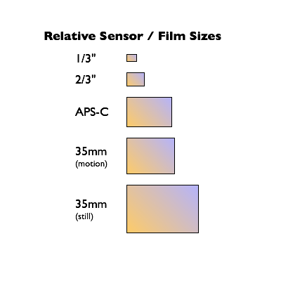
Sensor Format Size Comparison
The illustration below conceptually shows how common industrial sensor formats increase in physical size.
| Sensor Format | Relative Sensor Size | Typical Lens Type |
|---|---|---|
| 1/4″ | ■ | M12 Lens |
| 1/3″ | ■■ | M12 Lens |
| 1/2″ | ■■■ | M12 / FA Lens |
| 2/3″ | ■■■■ | FA Lens |
| 1″ | ■■■■■ | C Mount Lens |
| 1.1″ | ■■■■■■ | High-Resolution C Mount Lens |
Remember that larger sensors require lenses capable of projecting a larger image circle. Selecting an incompatible lens may cause dark corners (vignetting), reduced sharpness, or uneven illumination.
Understanding the relationship between sensor size and lens compatibility is the foundation of successful optical system design. The following sections will explain how sensor format influences field of view, image quality, and lens selection in practical machine vision applications.
How Sensor Format Affects Machine Vision Performance
Choosing the correct sensor format is about more than simply selecting a larger image sensor. Sensor size directly affects imaging performance, optical design, and overall system efficiency. Understanding these relationships helps engineers build machine vision systems that deliver accurate, reliable inspection results while keeping costs under control.
1. Field of View (FOV)
For the same focal length, a larger sensor captures a wider field of view because it records more of the image projected by the lens. This is particularly important for applications requiring full-object inspection or large-area monitoring.
Need to estimate your viewing area? Try our Interactive FOV Calculator.
2. Image Quality
Larger sensors generally collect more light, improving dynamic range, signal-to-noise ratio, and low-light performance. However, image quality also depends on lens performance, pixel size, illumination, and sensor technology.
3. Lens Compatibility
Every lens projects an image circle. If the image circle is smaller than the sensor, dark corners (vignetting) and reduced edge sharpness will occur. Proper sensor and lens matching is therefore essential.
4. Resolution
Higher-resolution sensors require lenses capable of resolving finer image details. Simply increasing megapixels without upgrading the lens rarely improves inspection accuracy.
5. Working Distance
Sensor size affects the required focal length for achieving a specific field of view. This relationship influences camera placement, installation space, and optical system design.
6. Total System Cost
Large sensors usually require larger image circles, higher-performance lenses, and more expensive cameras. Choosing the right sensor size—not simply the largest—is often the most cost-effective solution.
Sensor Format vs. Image Circle
One of the most common mistakes in industrial vision system design is overlooking the relationship between sensor format and lens image circle. Every industrial lens is designed to project a circular image. The sensor must fit entirely inside this image circle to capture a complete image without vignetting.
| Sensor Format | Typical Image Circle Requirement | Compatible Lens Types |
|---|---|---|
| 1/4″ | ≥4 mm | M12 Lens |
| 1/3″ | ≥6 mm | M12 Lens |
| 1/2″ | ≥8 mm | M12 / FA Lens |
| 2/3″ | ≥11 mm | FA Lens |
| 1″ | ≥16 mm | C Mount Lens |
Why Image Circle Matters
- Prevents image vignetting
- Maintains edge-to-edge sharpness
- Ensures uniform illumination
- Improves measurement accuracy
- Provides full sensor coverage
Image circle compatibility is one of the key topics discussed in our Optical Design Guide, where we explain how industrial lenses are optimized for different sensor sizes.
How to Match Sensor Formats with Industrial Lenses
Sensor selection should always be performed together with lens selection. Instead of choosing components independently, engineers should evaluate the complete imaging system—including sensor format, focal length, working distance, image circle, and application requirements.
| Sensor Format | Recommended Lens | Typical Mount | Recommended Applications |
|---|---|---|---|
| 1/3″ | M12 Lens (2.8–6 mm) | M12 | Security Cameras, Embedded Vision, AI Cameras |
| 1/2″ | M12 Lens (6–12 mm) | M12 | Machine Vision, Robotics, Barcode Reading |
| 2/3″ | FA Lens | C Mount | Industrial Inspection, Precision Measurement |
| 1″ | C Mount Lens | C Mount | AOI, Semiconductor Inspection, Medical Imaging |
Engineer Tip
Always confirm the camera’s sensor format before selecting a lens. Matching focal length alone is not enough—the lens must also provide an image circle large enough to fully cover the sensor.
For a complete workflow, refer to our Industrial Lens Selection Guide, which explains how sensor size, focal length, and working distance work together.
Real Machine Vision Application Examples
Different machine vision applications require different combinations of sensor formats and industrial lenses. The examples below illustrate common engineering practices.
| Application | Recommended Sensor | Typical Lens | Reason |
|---|---|---|---|
| PCB Inspection | 2/3″ | FA Lens | High measurement accuracy and edge sharpness |
| Robot Guidance | 1/2″ | M12 Lens | Compact size with balanced FOV |
| Medical Imaging | 1″ | Low Distortion C Mount Lens | High image quality and precise color reproduction |
| Traffic Monitoring | 1″ | Telephoto C Mount Lens | Long-distance object recognition |
| Smart Security | 1/2.8″ | M12 Lens | Wide field of view and low-light performance |
Explore more application-specific imaging solutions:
Understanding how sensor format affects optical performance allows engineers to choose the most appropriate camera and lens combination for each application. In the next section, we’ll examine the most common mistakes engineers make when selecting machine vision camera sensor formats—and how to avoid them.
Common Mistakes When Choosing Machine Vision Camera Sensor Formats
Selecting the correct sensor format is critical for achieving reliable imaging performance. However, many engineers focus only on camera specifications while overlooking how the sensor interacts with the optical system. Avoiding the following common mistakes can significantly improve image quality and reduce development costs.
❌ Choosing the Largest Sensor by Default
A larger sensor is not always the best choice. While larger sensors can provide a wider field of view and improved low-light performance, they also require larger image circles, higher-performance lenses, and a bigger overall budget.
❌ Ignoring Lens Image Circle
If the lens image circle is smaller than the sensor, vignetting, edge blur, and uneven illumination may occur. Always verify image circle compatibility before selecting a lens.
❌ Comparing Only Megapixels
High resolution alone does not guarantee better image quality. Pixel size, sensor technology, lens resolution, and optical quality all contribute to system performance.
❌ Forgetting the Working Distance
The required field of view depends on focal length, sensor size, and working distance together. These parameters should always be evaluated as a complete optical system.
❌ Selecting the Lens Before the Sensor
Industrial camera selection should begin with application requirements, followed by sensor format, focal length calculation, and finally lens selection.
❌ Ignoring Future System Expansion
If your project may require higher resolution in the future, consider selecting a lens capable of supporting larger sensors or higher megapixel cameras.
Continue Learning About Industrial Imaging
If you’re planning a complete machine vision system, the following resources will help you better understand industrial optics, image sensors, and lens selection.
Learn the fundamentals of CMOS sensors, rolling and global shutters, pixel size, image circle, and sensor selection.
Calculate field of view using sensor size, focal length, and working distance before selecting a lens.
Step-by-step guidance for selecting the right industrial lens for your imaging application.
Understand image circle, optical aberrations, lens optimization, and imaging performance.
Learn how barrel distortion, pincushion distortion, and optical correction influence industrial imaging accuracy.
Understand focal length, aperture, depth of field, image circle, and other essential optical concepts.
Frequently Asked Questions
Q: What is a machine vision camera sensor format?
A: A sensor format describes the physical size of a camera’s active imaging area. It influences field of view, image quality, lens compatibility, and overall imaging performance.
Q: Why isn’t a 1-inch sensor actually one inch?
A: The naming convention originates from historical television camera tube standards. Modern image sensors are significantly smaller than the fraction shown in their names.
Q: Does a larger sensor always produce better images?
A: Not necessarily. Larger sensors generally provide better low-light performance and wider fields of view, but system performance also depends on pixel size, lens quality, illumination, and optical design.
Q: How do I match a lens to my sensor?
A: Ensure the lens provides an image circle equal to or larger than the sensor format while selecting an appropriate focal length for the desired field of view.
Q: What is an image circle?
A: An image circle is the circular image projected by a lens. The entire sensor must fit inside this image circle to avoid vignetting.
Q: How does sensor format affect field of view?
A: For the same focal length, a larger sensor captures a wider field of view because it records a larger portion of the projected image.
Q: Which sensor format is best for machine vision?
A: There is no universal answer. The ideal sensor format depends on the application’s resolution, working distance, inspection accuracy, installation space, and budget.
Q: Can one industrial lens support multiple sensor formats?
A: Yes. If the lens provides a sufficiently large image circle, it can often support multiple sensor sizes that are equal to or smaller than its designed image circle.
Need Help Selecting the Right Sensor and Lens?
Choosing the right imaging system requires balancing sensor format, focal length, image circle, working distance, and application requirements. TOWIN’s optical engineering team can help you select or customize the ideal industrial lens solution for your project.
- ✔ Sensor and Lens Compatibility Analysis
- ✔ Machine Vision Lens Recommendations
- ✔ Optical Design Optimization
- ✔ OEM & ODM Lens Development
- ✔ Prototype Evaluation and Mass Production Support
Contact Our Engineering Team →
Conclusion
Machine Vision Camera Sensor Formats Explained is more than simply understanding sensor dimensions. Choosing the appropriate sensor format directly affects field of view, image quality, image circle compatibility, inspection accuracy, and the overall performance of an industrial vision system.
Rather than selecting the largest sensor available, engineers should evaluate the complete imaging system—including sensor format, lens resolution, focal length, working distance, optical design, and application requirements—to achieve the best balance between performance and cost.
For a deeper understanding of industrial image sensors and lens matching, continue exploring our Sensor Guide, use the FOV Calculator, and review our Lens Selection Guide before selecting your next machine vision camera.
We hope this guide on Machine Vision Camera Sensor Formats Explained helps you confidently choose the right sensor and optical solution for your industrial imaging application.