


1/2″ 30mm IR corrected CCTV M12 Pinhole lens
01/14/2026
Low distortion CCTV 12mm M12 lens
01/15/2026
A low distortion lens is designed to minimize geometric deformation in an image, helping machine vision systems capture object shapes and positions more accurately. In industrial inspection, lens distortion can affect dimensional measurement, part alignment, defect localization, and other vision-based tasks. Choosing the right lens requires more than looking at the distortion specification alone. Sensor size, focal length, field of view (FOV), resolution, working distance, and calibration all influence the final imaging result.
This guide explains how low distortion lenses work, why distortion matters in precision inspection, and how to select an appropriate lens for your application. You can also explore TOWIN’s low distortion lens products to compare available specifications.
What Is a Low Distortion Lens?
A low distortion lens is an optical lens engineered to limit changes in image magnification across the field of view. With a lens that has significant geometric distortion, straight lines may appear curved and the apparent dimensions of an object may vary with its position in the image. A low distortion optical design reduces these geometric deviations, making the image more suitable for measurement, inspection, and positioning tasks.
Lens distortion is different from blur. Blur reduces the visibility of fine details, while geometric distortion changes where image points appear. A lens can have high resolution but still exhibit noticeable distortion. For this reason, resolution and distortion should be evaluated as separate optical performance parameters.
Common Types of Lens Distortion
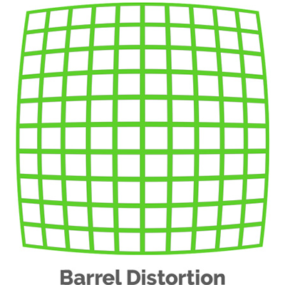
- Barrel distortion: Straight lines near the image edges bend outward. This is commonly associated with wide-angle optical designs.
- Pincushion distortion: Straight lines near the image edges bend inward. The effect may appear in some longer-focal-length optical systems.
- Mustache or complex distortion: The distortion pattern changes across the image and may combine barrel-like and pincushion-like behavior.
Distortion performance is often expressed as a percentage, but values should only be compared when their measurement definitions and test conditions are consistent. TV distortion, geometric distortion, and residual distortion after software correction are not automatically equivalent.
For a more detailed explanation of distortion types and their effects on imaging, read TOWIN’s lens distortion guide.
Why Does Low Distortion Matter in Precision Inspection?
In machine vision, an image is often used to measure dimensions, locate features, compare shapes, or guide automated equipment. If the optical system introduces geometric distortion, the relationship between image coordinates and real-world coordinates becomes more complicated. A properly selected low distortion lens can reduce one source of geometric error and simplify the development of a reliable inspection system.
1. Dimensional Measurement
Dimensional inspection systems measure features such as component width, hole spacing, edge position, and surface geometry. When distortion is not adequately controlled or compensated for, measurement results may vary depending on where a feature appears in the image.
A low distortion lens can help reduce this source of variation. However, measurement accuracy also depends on pixel scale, camera calibration, object positioning, lighting, mechanical stability, and the measurement algorithm.
2. Component Alignment and Positioning
Automated assembly and robotic guidance systems rely on accurate feature coordinates. Geometric distortion can affect the apparent position of features across the image, potentially complicating alignment and coordinate mapping. Low distortion optics can be particularly useful when features must be located consistently over a relatively large inspection area.
Explore TOWIN’s machine vision applications to learn more about optical requirements for industrial imaging systems.
3. PCB and Electronic Component Inspection
Printed circuit boards and electronic components often contain small features that must be measured or located precisely. A suitable lens should provide the required resolution while controlling distortion over the region of interest. The appropriate choice depends on the component size, camera sensor, working distance, field of view, and inspection tolerance.
4. Automated Defect Localization
Machine vision algorithms may use image coordinates to identify scratches, missing components, surface defects, or dimensional deviations. Geometric distortion can influence feature localization, particularly when a system operates across a wide image area. Low distortion optics can help maintain a more consistent geometric relationship between the object and its image.
Low distortion alone does not guarantee better defect detection. Image sharpness, contrast, illumination, sensor performance, and algorithm design remain important.
How to Choose a Low Distortion Lens for Industrial Inspection
Selecting a low distortion lens for industrial inspection requires evaluating the entire optical system rather than choosing a lens based on one specification. Use the following criteria to narrow down suitable options.
1. Define the Required Distortion Performance
Start by determining the maximum geometric error that your application can tolerate. A dimensional measurement system may require tighter distortion control than a general monitoring camera. The appropriate target depends on the measurement tolerance, image scale, calibration method, and distribution of features across the image.
Ask the lens supplier how distortion is defined and measured. Confirm whether the specification represents TV distortion, another geometric distortion metric, or residual distortion after correction. Also check whether the value applies to the complete image area and the intended operating configuration.
2. Match the Lens to the Camera Sensor
The lens image format must adequately cover the camera sensor. Sensor format labels such as 1/2 inch, 1/1.8 inch, and 2/3 inch are commonly used in industrial imaging, but they are nominal optical formats rather than direct measurements of the sensor diagonal.
If you are searching for a 1/2-inch low distortion lens, confirm the actual sensor dimensions, required image circle, focal length, and field of view. Sensor compatibility alone does not establish that a lens will meet the required distortion or measurement tolerance.
Use TOWIN’s lens selection guide to review the main factors involved in matching a lens to an industrial camera.
3. Calculate Focal Length and Field of View
Focal length and sensor dimensions determine the field of view for a given optical configuration. Working distance and the size of the target area also influence the focal length required for an application. A lens with insufficient coverage may miss important features, while an unnecessarily wide field of view may reduce the image scale available for measurement.
For a first-order estimate of a rectilinear imaging system, horizontal field of view can be approximated by:
Horizontal FOV ≈ 2 × arctan(sensor width / (2 × focal length))
This simplified relationship assumes an idealized optical model. Actual field of view depends on lens design, distortion, focus configuration, and other optical factors.
Use the TOWIN field of view calculator to estimate the viewing area based on sensor size, focal length, and working distance.
4. Check Resolution and Image Quality
A low distortion lens must also resolve the details required by the inspection task. Compare the lens’s supported resolution and optical performance with the camera sensor, pixel size, and size of the smallest feature to be detected.
Resolution, contrast, distortion, and illumination should be considered together. A lens with low distortion may still be unsuitable if its edge sharpness, light transmission, or image coverage does not meet the application’s requirements.
5. Confirm Mount Type and Mechanical Compatibility
The lens mount must match the camera or its approved mechanical interface. M12/S-Mount lenses are commonly used in compact embedded cameras, while C-Mount lenses are widely used in industrial imaging systems. CS-Mount lenses are also used in selected camera applications.
Confirm thread dimensions, flange distance, back focal requirements, lens clearance, and available adjustment range before finalizing a selection. Browse the relevant M12/S-Mount lenses or C-Mount lenses to explore available product families.
6. Consider Aperture, Lighting, and Working Distance
Aperture affects the amount of light reaching the sensor and the depth of field. The required aperture depends on illumination, exposure time, object movement, and the depth range that must remain in focus. Working distance also affects image scale, lens positioning, and system packaging.
Evaluate the lens under the intended operating conditions rather than assuming that a low distortion specification guarantees the same imaging performance in every setup.
7. Plan for Calibration and System Validation
Even a low distortion lens may require calibration for precision measurement. Calibration establishes the relationship between image coordinates and physical coordinates under defined operating conditions. The required procedure depends on the application, measurement tolerance, camera geometry, and whether the system uses telecentric or conventional optics.
Validate the complete system using appropriate calibration targets and representative inspection parts. If the camera, lens focus, working distance, or mechanical setup changes, determine whether recalibration is necessary.
How to Evaluate Low Distortion Lens Specifications
Before purchasing a low distortion lens, compare the following parameters with the actual requirements of your camera and inspection task.
| Parameter | What to Check | Why It Matters |
|---|---|---|
| Distortion | Metric, percentage, test conditions | Indicates geometric deformation under the stated test method. |
| Sensor format | Sensor dimensions and image circle | Helps prevent image cropping and inadequate sensor coverage. |
| Focal length | Effective focal length and required FOV | Determines the framing and image scale for the setup. |
| Resolution | Sensor pixel size and lens performance | Helps ensure that required details can be resolved. |
| Working distance | Object distance and available installation space | Affects focus, field of view, and mechanical layout. |
| Aperture | F-number and lighting conditions | Influences image brightness and depth of field. |
| Mount | M12, C-Mount, CS-Mount, or another interface | Ensures mechanical and optical compatibility. |
TOWIN provides a range of low distortion lens options for different sensor formats and imaging requirements. Compare the published specifications carefully and request clarification if a parameter or test definition is not available.
Low Distortion Lens vs. Software Distortion Correction
Optical distortion control and software correction address related but different parts of an imaging system. A low distortion lens reduces geometric deformation optically. Software correction uses a calibration model to remap image coordinates and compensate for measured distortion.
Software correction can be useful when residual distortion must be reduced or when an existing camera system cannot be replaced. However, remapping may require interpolation, additional processing, and image cropping near the boundaries. The resulting image should be validated for the required measurement task.
Using low distortion optics can reduce the amount of geometric correction required, but it does not automatically eliminate calibration or software processing. The best approach depends on the accuracy target, processing resources, field of view, and overall system design.
For applications with demanding optical requirements, review TOWIN’s optical design resources to understand how distortion, resolution, field of view, and other optical factors interact.
Applications of Low Distortion Lenses
Industrial Measurement and Inspection
Low distortion lenses can support dimension measurement, part positioning, component inspection, and automated quality control when geometric consistency is important.
PCB and Electronic Assembly
Electronic inspection systems may use low distortion optics to locate component edges, compare layouts, and measure feature positions. The required lens depends on board size, feature dimensions, camera resolution, and inspection tolerance.
Robotics and Automated Guidance
Vision-guided robots use image coordinates to estimate object position and orientation. A well-matched low distortion lens can help maintain consistent geometric relationships across the working area, supporting calibration and coordinate mapping.
Metrology and Automated Measurement
Optical measurement systems must account for the complete measurement chain, including lens distortion, sensor sampling, calibration, mounting stability, and the measurement algorithm. Low distortion optics are one part of a properly validated system.
If your project has specific imaging requirements, explore TOWIN’s industrial optical solutions for different vision applications.
Frequently Asked Questions About Low Distortion Lenses
1. What is considered a low distortion lens?
A low distortion lens is designed to limit geometric image deformation. There is no single distortion percentage that is suitable for every application. The acceptable value depends on the measurement tolerance, field of view, calibration method, and distortion metric used in the specification.
2. Is a low distortion lens always better for machine vision?
Not necessarily. Low distortion is especially useful for geometric measurement, alignment, and positioning, but a lens must also meet requirements for resolution, field of view, aperture, working distance, and cost. Other applications may prioritize wide-angle coverage or light sensitivity.
3. How do I choose a 1/2-inch low distortion lens?
First confirm that the lens covers the camera sensor. Then compare focal length, field of view, distortion specification, resolution, working distance, and mount type. If dimensional measurement is involved, validate the selected lens with the intended camera and calibration setup.
4. Does a low distortion lens eliminate the need for calibration?
No. Low distortion optics can reduce one source of geometric error, but precision measurement systems may still require calibration. The calibration method and frequency should be based on the application’s accuracy requirements and operating conditions.
5. Can software correct lens distortion?
Yes. Calibration-based software correction can compensate for measured geometric distortion. However, the process may involve interpolation, processing overhead, and edge cropping. Validate the corrected image to ensure that it meets the application’s measurement and image-quality requirements.
6. Which specifications should I provide when requesting a low distortion lens?
Provide your camera model or sensor dimensions, resolution, required field of view, working distance, target object size, acceptable distortion or measurement tolerance, lighting conditions, mount type, and installation constraints. These details help an optical engineer identify suitable products or assess whether a custom solution is required.
Choose the Right Low Distortion Lens for Your Application
Choosing the right low distortion lens starts with a clear understanding of your measurement requirements, camera sensor, field of view, working distance, and optical performance targets. Distortion should be evaluated alongside resolution, illumination, mechanical compatibility, and calibration rather than treated as an isolated specification.
Explore TOWIN’s low distortion lens catalog to compare available options. If you need help matching a lens to your camera or industrial inspection system, please contact the TOWIN team with your sensor size, focal length or FOV requirement, working distance, and target distortion specification.