ADAS Camera Lens Specifications: A Comprehensive Guide for Automotive Vision
03/15/2026
Choosing Between Fixed Focal and Varifocal Lenses
03/17/2026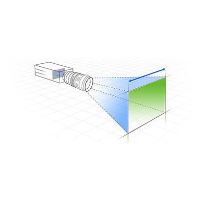
Table of Contents
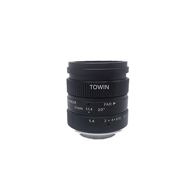
Field of View (FOV) is the core parameter of machine vision systems that determines the observable range of the camera-lens combination. Accurate FOV calculation is the foundation of selecting industrial lenses, building stable vision systems, and ensuring the accuracy of detection and measurement. As a professional optical lens supplier, TOWIN not only provides a full range of machine vision lenses (C-mount, CS-mount, M12/S-mount) but also launches a free FOV Calculator to help you quickly get accurate FOV values. This article will detail the core formulas, key parameters, calculation steps, influence factors and lens selection skills of machine vision FOV calculation.
Key Parameters for Machine Vision FOV Calculation
FOV calculation is based on the geometric optical relationship between the lens and the camera sensor, and the accuracy of core parameters directly determines the calculation result. All parameters need to use a unified unit (mm is recommended for industrial applications).
Core Basic Parameters
- Sensor Size (SS): The effective imaging area of the camera’s CCD/CMOS sensor, the most critical parameter for FOV calculation. Common sizes are 1/4″, 1/3″, 1/2″, 2/3″, 1″ (the horizontal/vertical dimensions of different sizes are fixed industry standards).
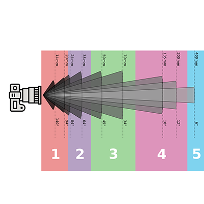
- Focal Length (FL): The distance from the optical rear principal point of the lens to the focal point, in mm. It is the core parameter of the lens and directly affects the FOV size (the longer the focal length, the smaller the FOV).
- Working Distance (WD): The actual straight-line distance from the front end of the lens to the measured object, excluding the distance from the sensor to the lens. This is the most easily confused parameter in calculation and must be distinguished from the object-to-image distance.
- Magnification (PMAG): The ratio of the image size on the sensor to the actual size of the measured object, which is the bridge between the sensor size and the actual FOV.
Standard Sensor Size Specifications (Industry Universal)
| Sensor Size | Horizontal Dimension (mm) | Vertical Dimension (mm) | Typical Application |
| 1/4″ | 3.2 | 2.4 | Miniature machine vision, compact detection |
| 1/3″ | 4.8 | 3.6 | General industrial detection, CCTV |
| 1/2″ | 6.4 | 4.8 | High-precision measurement, 5MP machine vision (TOWIN hot sale) |
| 2/3″ | 8.8 | 6.6 | High-resolution detection, professional measurement |
| 1″ | 12.8 | 9.6 | Ultra-high precision industrial inspection, 3D vision |
Core Formulas for Machine Vision FOV Calculation
FOV calculation has two core derivation forms, which are applicable to direct manual calculation and system parameter matching respectively. The two formulas can be converted to each other and are suitable for different application scenarios of machine vision. All formulas are based on the ideal rectilinear lens model (for fisheye/wide-angle lenses with large distortion, refer to the product datasheet for correction).
Formula 1: FOV Calculation Based on Sensor Size & Magnification
Suitable for scenarios where the lens magnification is known (e.g., macro lens, telecentric lens application).
- FOV (Actual Field of View) = Sensor Size (SS) / Magnification (PMAG)
- Horizontal FOV = Horizontal Sensor Dimension / PMAG
- Vertical FOV = Vertical Sensor Dimension / PMAG
Formula 2: FOV Calculation Based on Focal Length & Working Distance
The most commonly used formula in industrial applications, suitable for most standard machine vision lenses (C-mount/CS-mount/M12). It is the theoretical basis of TOWIN FOV Calculator.
- FOV = (Sensor Size × Working Distance) / Focal Length
- Horizontal FOV (H-FOV) = (Horizontal SS × WD) / FL
- Vertical FOV (V-FOV) = (Vertical SS × WD) / FL
Supplementary Formula: Magnification & Focal Length Conversion
PMAG = FL / (WD – FL)
This formula can realize the mutual conversion of the two core calculation methods, which is convenient for parameter verification and double-checking of calculation results.
Quick Example of Manual Calculation
Take TOWIN FOV Calculator default parameters as an example: 1/2″ sensor (6.4×4.8mm), focal length 4.0mm, working distance 3000mm (3m).
- Horizontal FOV = (6.4 × 3000) / 4.0 = 4800mm = 4.8m
- Theoretical horizontal FOV angle = 77.3° (consistent with the calculator result)
- TOWIN CCL12044MPF lens has a nominal H-FOV of 77°, with a deviation of only 0.3°, which is far higher than the industry ±5° standard.
Step-by-Step FOV Calculation for Machine Vision
Follow the following 5 steps to complete the FOV calculation, which is applicable to all machine vision application scenarios (from simple detection to high-precision measurement). The whole process can be completed in 2 minutes, and the TOWIN FOV Calculator can skip manual calculation and directly get the result with one click.
Step 1: Confirm the Camera Sensor Size
Check the official datasheet of the camera to get the actual horizontal/vertical effective dimensions (not just the nominal size such as 1/2″). Ensure the unit is unified to mm.
Step 2: Determine the Actual Working Distance (WD)
Measure the straight-line distance from the lens mounting surface to the measured object according to the on-site application environment (e.g., 200mm for industrial assembly line detection, 3000mm for long-distance monitoring). Do not estimate—use a caliper/laser range finder for accurate measurement.
Step 3: Select the Lens Focal Length (FL)
According to the expected FOV range, select the corresponding focal length of TOWIN machine vision lens (C-mount/CS-mount/M12 are all available with multiple focal lengths). If the FOV is unknown, you can reverse calculate the required focal length through the expected FOV.
Step 4: Choose the Appropriate Core Formula for Calculation
- Use Formula 1 if the lens magnification is known (telecentric lens/macro lens)
- Use Formula 2 for standard industrial lenses (the most commonly used)
- Calculate the horizontal/vertical FOV respectively, and check the results with the magnification conversion formula.
Step 5: Correct for Lens Distortion
For wide-angle/fisheye lenses with distortion >1%, refer to the TOWIN product datasheet for the actual FOV correction value. For standard low-distortion machine vision lenses (distortion <1%), no correction is needed, and the theoretical calculation result is directly used.
One-Click Calculation with TOWIN FOV Calculator
To save time and avoid manual calculation errors, TOWIN’s exclusive FOV Calculator is the best choice:
- Select the sensor size (supports all standard sizes such as 1/2″, 1/3″)
- Enter the lens focal length (mm) and actual working distance (m)
- Click to calculate, and get the theoretical horizontal FOV angle in real time
- Check the matching TOWIN lens model and its nominal FOV (with ±5° industry standard deviation)

FOV Calculation
Key Factors Affecting Machine Vision FOV
The theoretical FOV calculation is based on the ideal optical model, but the actual FOV in the industrial field will be affected by multiple factors. Ignoring these factors will lead to the mismatch between the calculated value and the actual application effect. TOWIN lenses optimize all influence factors through professional optical design to ensure the consistency of theoretical and actual FOV.
1. Lens Distortion
- Radial distortion (barrel/pincushion) is the main factor affecting FOV, especially for wide-angle/fisheye lenses (distortion >5%).
- TOWIN low-distortion machine vision lenses (C-mount/CS-mount) have a distortion rate of <0.5%, which can basically eliminate the FOV deviation caused by distortion.
2. Sensor Pixel and Resolution
- The actual effective FOV is limited by the camera pixel resolution (low pixel will cause the edge of the FOV to be blurred and unrecognizable).
- It is recommended to match TOWIN high-resolution lenses with megapixel cameras (e.g., 5MP 1/2″ sensor with TOWIN CCL121625MPRF lens).
3. Working Distance Deviation
- On-site vibration (assembly line, mechanical arm) will cause the change of WD, which directly leads to FOV shift.
- For dynamic application scenarios, select TOWIN lenses with large depth of field (DOF) to reduce the impact of WD deviation.
4. Lens Mount Type
- C-mount (flange focal distance 17.526mm) and CS-mount (12.526mm) have fixed flange distances. Incorrect matching (e.g., C-mount lens with CS-mount camera without adapter ring) will cause defocus and FOV reduction.
- TOWIN provides a full range of C/CS/M12 mount lenses and matching adapter rings to ensure standard mounting.
5. Environmental Factors
- High temperature/humidity will cause slight deformation of the lens optical components, leading to micro FOV deviation (applicable to high-precision measurement scenarios).
- TOWIN industrial lenses use high-temperature resistant optical glass and metal shells, which can adapt to -20℃~+60℃ industrial environment.
Machine Vision FOV Application Scenarios
Different machine vision application scenarios have different FOV requirements, and the matching lens focal length, mount type and working distance are also different. TOWIN has a full range of lenses for all scenarios, and the FOV can be customized according to customer needs. The following are the typical application scenarios and FOV matching principles:
1. Industrial Assembly Line Detection
- FOV requirement: Medium range (0.5m~2m), high uniformity, low distortion
- Working distance: 100mm~500mm
- TOWIN lens recommendation: C-mount low-distortion lenses (MV/FA lens), 8mm~25mm focal length
- Typical application: Electronic component defect detection, product size sorting
2. High-Precision Industrial Measurement
- FOV requirement: Small range (0.05m~0.5m), ultra-high precision, no distortion
- Working distance: 50mm~200mm
- TOWIN lens recommendation: C-mount telecentric lenses, 12mm~35mm focal length
- Typical application: Precision mechanical part size measurement, semiconductor wafer detection
3. Intelligent Traffic System (ITS) Monitoring
- FOV requirement: Large range (5m~50m), wide angle, long working distance
- Working distance: 3m~10m
- TOWIN lens recommendation: C-mount traffic lenses (ITS lens), 4mm~16mm wide-angle focal length
- Typical application: Road vehicle detection, parking lot monitoring
4. Miniature Vision System (PCB/Medical)
- FOV requirement: Micro range (0.01m~0.1m), compact size
- Working distance: 10mm~50mm
- TOWIN lens recommendation: M12/S-mount miniature lenses (board lens), 2.8mm~8mm focal length
- Typical application: PCB board detection, medical device micro-detection
5. 3D Machine Vision
- FOV requirement: Medium range (0.3m~3m), high consistency, large depth of field
- Working distance: 200mm~800mm
- TOWIN lens recommendation: C-mount high-resolution lenses, 16mm~35mm focal length
- Typical application: 3D scanning, mechanical arm positioning, object recognition

FOV Calculation
Machine Vision Lens Selection Based on FOV Requirements
FOV is the core basis of lens selection. The wrong selection will lead to the failure of the vision system to detect/measure normally. TOWIN summarizes the 5 core selection principles based on more than 10 years of optical lens R&D and production experience, which can help you quickly select the most suitable machine vision lens according to the FOV calculation results.
Core Selection Principles
- Match sensor size first: The lens imaging surface size must be ≥ the camera sensor size (e.g., 1/2″ sensor with ≥1/2″ lens). TOWIN lenses are marked with clear sensor size matching to avoid mismatch.
- Determine focal length by FOV/WD: According to the FOV calculation formula, reverse calculate the required focal length (FL = SS×WD/FOV). TOWIN provides multiple focal lengths for each mount type (4mm~50mm) to choose from.
- Select mount type by application: M12 for miniature systems, CS-mount for general surveillance, C-mount for industrial machine vision/ITS (TOWIN’s main product line).
- Consider distortion and resolution: For measurement scenarios, select low-distortion (<0.5%) and high-resolution lenses; for general detection, standard lenses can meet the requirements.
- Customize FOV if needed: TOWIN supports ODM/OEM custom lens design, and can customize the focal length, FOV and working distance according to the actual on-site FOV requirements.
TOWIN Lens Mount Type & FOV Matching Table
| Mount Type | Focal Length Range (mm) | Typical FOV Angle (1/2″ sensor, WD=1m) | Core Application |
| M12/S-mount | 2.8~16 | 90°~25° | Miniature vision, PCB detection |
| CS-mount | 4~35 | 80°~15° | Video surveillance, general detection |
| C-mount | 4~50 | 80°~10° | Machine vision, ITS, 3D vision |
Final Tips for Machine Vision FOV Calculation
- 1. Unify units: All parameters use mm for calculation to avoid unit conversion errors (the most common manual calculation mistake).
- 2. Use TOWIN FOV Calculator: One-click calculation without manual formula application, and the result is consistent with the actual lens FOV.
- 3. Verify with actual measurement: After theoretical calculation, use the actual lens-camera combination to test the on-site FOV and fine-tune the working distance/focal length.
- 4. Choose professional lenses: TOWIN machine vision lenses (C/CS/M12) are designed for industrial applications, with the theoretical FOV highly consistent with the actual FOV, and provide a 1-year after-sales warranty.
About TOWIN
TOWIN is a professional optical lens supplier in China, focusing on the R&D, production and customization of machine vision lenses (C-mount, CS-mount, M12/S-mount). We adhere to the concept of PROFESSIONAL-ALL-EASY-FAST, provide a full range of optical lens solutions for global customers, and support ODM/OEM custom design. If you have any questions about FOV calculation or lens selection, please contact us via info@towin-elec.com, and our professional optical engineers will reply you within 24 hours.
Click to use TOWIN FOV Calculator now: https://www.towinlens.com/fov-calculator.html