


Why Is Optical Design Important for Industrial Lenses?
07/13/2026
How Does Sensor Size Affect Optical Design?
07/15/2026
What is Optical Design in Machine Vision? It is the process of designing and optimizing an optical system that enables industrial cameras to capture accurate, repeatable, and high-quality images for automated inspection, measurement, positioning, and artificial intelligence (AI) vision applications. Unlike consumer photography, where visual appearance is the primary goal, machine vision optical design focuses on precision, consistency, and imaging reliability under demanding industrial conditions.
A well-designed machine vision lens does much more than simply produce a sharp image. It must balance multiple optical parameters—including resolution, MTF (Modulation Transfer Function), distortion, field of view (FOV), chief ray angle (CRA), relative illumination, depth of field (DOF), and sensor compatibility—to ensure that every captured image contains reliable data for downstream image processing algorithms.
Whether you’re building an automated inspection system, developing an AI-powered vision solution, or selecting an industrial lens for robotics, understanding machine vision optical design is essential for achieving accurate imaging performance.
In this guide, you’ll learn how machine vision optical systems work, which optical parameters matter most, how engineers optimize industrial lenses, and how to choose the right optical solution for your application. If you’re new to industrial optics, we recommend first exploring our comprehensive Optical Design Guide, which introduces the core principles behind industrial lens engineering.
What Is Optical Design in Machine Vision?
Machine vision optical design is the engineering process of creating an optical system that delivers accurate image information from an object to an image sensor. Unlike general-purpose photography, machine vision requires predictable optical performance because every captured pixel may influence measurement accuracy, defect detection, robotic positioning, or AI decision-making.
A complete machine vision imaging system typically consists of the following components:
| Component | Function |
|---|---|
| Object | The target being inspected or measured. |
| Lighting | Provides stable illumination for image capture. |
| Lens | Collects and focuses light onto the sensor. |
| Image Sensor | Converts optical information into digital signals. |
| Vision Software | Processes images for inspection or analysis. |
| PLC / AI System | Makes automated decisions based on image data. |
Among these components, the lens acts as the foundation of the imaging system. Even the highest-resolution image sensor cannot compensate for poor optical quality. If the optical design introduces distortion, blur, low contrast, or uneven illumination, the resulting image data becomes less reliable regardless of the processing software.
Machine Vision Imaging Workflow
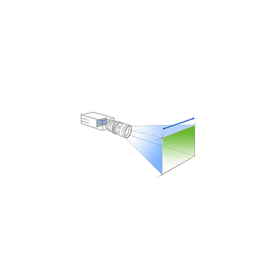
The following simplified workflow illustrates how optical design fits into a complete machine vision system:
- Object reflects or emits light.
- Lighting creates consistent illumination.
- Industrial lens focuses light onto the sensor.
- Image sensor captures optical information.
- Vision software analyzes image features.
- AI or PLC executes automated decisions.
Every stage depends on the quality of the optical system. This is why optical design is often considered the first step in building a reliable machine vision solution.
Why Optical Design Matters in Machine Vision
Consumer cameras are designed to create visually appealing photographs. Machine vision systems, however, are engineered to make objective decisions based on image data. A slight reduction in image quality may lead to incorrect measurements, failed inspections, or inaccurate AI recognition.
For example, an automated PCB inspection system may need to detect solder defects smaller than 50 microns. A robotic guidance system must identify object edges consistently under varying lighting conditions. In these scenarios, the optical system becomes a critical factor in the overall accuracy of the entire production process.
Machine vision optical design ensures that images remain:
- High in resolution
- Low in distortion
- Consistent from center to edge
- Uniform in brightness
- Compatible with the selected sensor
- Stable under industrial operating conditions
Achieving these objectives requires balancing multiple optical parameters rather than maximizing only one specification.
Machine Vision vs Consumer Camera Optical Design
| Performance Requirement | Consumer Camera | Machine Vision |
|---|---|---|
| Image Resolution | High | Very High |
| Optical Distortion | Acceptable | Minimal (<1% preferred) |
| MTF Performance | Good | Excellent Across Entire Sensor |
| Repeatability | Moderate | Critical |
| Measurement Accuracy | Not Required | Essential |
| Sensor Compatibility | Limited Importance | Critical |
| Chief Ray Angle (CRA) | Low Priority | High Priority |
| Relative Illumination | Moderate | High Uniformity Required |
This comparison highlights why industrial optical systems require much tighter engineering tolerances than conventional photography lenses. Instead of optimizing solely for aesthetics, machine vision lenses must produce measurable, repeatable, and geometrically accurate images.
The Primary Goals of Machine Vision Optical Design
During the optical design process, engineers optimize the lens according to the application’s imaging requirements rather than focusing on a single specification.
The most common design objectives include:
- Maximize image sharpness across the entire sensor.
- Minimize optical distortion for accurate measurement.
- Maintain high MTF at required spatial frequencies.
- Provide sufficient depth of field for stable focusing.
- Optimize chief ray angle (CRA) for sensor compatibility.
- Maintain high relative illumination to reduce edge darkening.
- Reduce chromatic and spherical aberrations.
- Achieve consistent imaging under industrial environments.
These objectives work together to ensure that every captured image contains reliable information for automated inspection systems, robotics, AI vision, and precision measurement.
Many of these concepts are explained in greater detail throughout our Knowledge Center, including:
Key Optical Parameters in Machine Vision
Successful machine vision systems are never designed around a single specification. Instead, engineers optimize multiple optical parameters simultaneously to achieve the desired balance between image quality, measurement accuracy, field coverage, and system cost.
When discussing What is Optical Design in Machine Vision, these parameters form the foundation of every industrial optical system. Each parameter influences imaging performance in a different way, and improving one characteristic often requires trade-offs with another.
Below are the most important optical parameters considered during machine vision lens design.
1. Resolution
Resolution describes the optical system’s ability to reproduce fine details. As modern industrial cameras continue to increase from 2MP to 20MP and beyond, lenses must provide sufficient resolving power to fully utilize the sensor.
| Importance | Typical Value | Why It Matters |
|---|---|---|
| ★★★★★ | 2MP–25MP+ | Determines the smallest detectable feature. |
High-resolution imaging is especially important for PCB inspection, semiconductor manufacturing, and precision metrology.
2. Modulation Transfer Function (MTF)
MTF measures how efficiently the lens transfers image contrast from the object to the sensor. Unlike megapixel ratings, MTF reflects real imaging performance across different spatial frequencies.
| Importance | Typical Requirement | Why It Matters |
|---|---|---|
| ★★★★★ | >0.6 @ Required Spatial Frequency | Determines image sharpness and contrast. |
To understand this topic in greater depth, read our guide What Is MTF in Optical Design?
3. Lens Distortion
Lens distortion refers to geometric deformation caused by the optical system. Excessive distortion introduces measurement errors and reduces positioning accuracy.
| Importance | Typical Target | Why It Matters |
|---|---|---|
| ★★★★★ | <1% | Critical for precision measurement. |
Applications such as robot calibration, dimensional inspection, and automated measurement typically require low-distortion optical systems.
Related reading: Lens Distortion Guide.
4. Field of View (FOV)
The field of view defines the physical area captured by the camera. Selecting the correct FOV ensures that the entire inspection target fits within the image while maintaining sufficient image resolution.
| Importance | Depends On | Why It Matters |
|---|---|---|
| ★★★★★ | Sensor Size + Focal Length + Working Distance | Determines inspection coverage. |
Need help calculating FOV? Try our Interactive FOV Calculator.
5. Chief Ray Angle (CRA)
Chief Ray Angle describes the angle at which light reaches the image sensor. Modern CMOS sensors often require carefully controlled CRA values to maintain image brightness and reduce edge shading.
| Importance | Typical Requirement | Why It Matters |
|---|---|---|
| ★★★★☆ | <10° (Application Dependent) | Improves sensor compatibility. |
6. Relative Illumination
Relative illumination measures brightness uniformity from the image center to the corners. Poor relative illumination causes noticeable vignetting and uneven exposure.
| Importance | Typical Target | Why It Matters |
|---|---|---|
| ★★★★☆ | >70% | Ensures consistent image brightness. |
7. Depth of Field (DOF)
Depth of field represents the range within which objects remain acceptably sharp. Machine vision systems often require sufficient DOF to compensate for object height variations during inspection.
| Importance | Affected By | Why It Matters |
|---|---|---|
| ★★★★☆ | F-number, Focal Length, Working Distance | Maintains focus consistency. |
8. Image Circle
The image circle must completely cover the sensor. If the image circle is too small, severe corner darkening or cropping will occur.
| Importance | Selection Basis | Why It Matters |
|---|---|---|
| ★★★★☆ | Sensor Size | Ensures full sensor coverage. |
Machine Vision Optical Parameter Comparison
Although every application has unique requirements, the following table summarizes the most common target values used in industrial imaging systems.
| Parameter | Importance | Typical Target | Primary Purpose |
|---|---|---|---|
| Resolution | ★★★★★ | 5–20MP+ | Capture fine details |
| MTF | ★★★★★ | >0.6 | Improve sharpness |
| Distortion | ★★★★★ | <1% | Measurement accuracy |
| FOV | ★★★★★ | Application Specific | Inspection coverage |
| CRA | ★★★★☆ | <10° | Sensor compatibility |
| Relative Illumination | ★★★★☆ | >70% | Brightness uniformity |
| Depth of Field | ★★★★☆ | Application Specific | Focus stability |
| Image Circle | ★★★★☆ | Matches Sensor | Complete image coverage |
How Optical Design Affects Machine Vision Accuracy
Every optical parameter directly influences the performance of the entire vision system. Even a small reduction in optical quality may result in inaccurate measurements, unstable robot positioning, or false defect detection.
| Optical Parameter | Influence on Machine Vision |
|---|---|
| Resolution | Determines minimum detectable feature size. |
| MTF | Improves image sharpness and edge definition. |
| Distortion | Reduces dimensional measurement error. |
| Relative Illumination | Improves brightness consistency. |
| CRA | Enhances CMOS sensor compatibility. |
| DOF | Maintains focus despite object height variation. |
| FOV | Ensures complete inspection coverage. |
For example, a high-resolution camera paired with a low-MTF lens may produce images that appear soft, reducing defect detection accuracy. Likewise, a lens with excessive distortion can compromise dimensional measurements even if the image appears visually sharp.
This is why experienced optical engineers optimize the complete imaging system rather than focusing on individual specifications.
Machine Vision Optical Design Workflow
Developing a high-performance machine vision lens follows a structured engineering workflow. Each stage builds upon the previous one to ensure the final optical system satisfies both imaging requirements and manufacturing constraints.
- Define application requirements.
- Select the appropriate image sensor.
- Calculate field of view and working distance.
- Determine lens architecture.
- Perform optical simulation and optimization.
- Analyze MTF, distortion, and aberrations.
- Build prototype lenses.
- Validate optical performance.
- Mass production and quality inspection.
This workflow integrates optical theory with real-world manufacturing, ensuring consistent imaging performance across production batches.
Machine Vision Optical Design Across Different Applications
Although the fundamental principles of optical engineering remain consistent, What is Optical Design in Machine Vision varies depending on the application. Every industry has unique imaging requirements, inspection targets, environmental conditions, and accuracy expectations. As a result, engineers optimize different optical parameters for different machine vision systems.
For example, a semiconductor inspection system focuses on achieving extremely high MTF and minimal distortion, while a robotic guidance system may prioritize wide field of view and large depth of field. Understanding these application-specific priorities helps engineers choose the right optical solution instead of relying on generic specifications.
Application Matrix
| Application | Primary Optical Requirement | Typical Lens Type |
|---|---|---|
| PCB Inspection | Low Distortion + High Resolution | FA Lens |
| Semiconductor Inspection | Ultra-High MTF | Telecentric Lens |
| Robot Vision | Wide FOV + Large DOF | M12 Lens |
| Barcode & OCR | High Contrast | C-Mount Lens |
| Precision Measurement | Telecentric Imaging | Telecentric Lens |
| Medical Imaging | High Resolution + Uniform Brightness | Low Distortion Lens |
| Smart Traffic | Long Working Distance | C-Mount Lens |
| Biometric Recognition | Excellent NIR Performance | M12 Lens |
To explore these applications in greater detail, visit our dedicated solution pages:
How to Choose the Right Machine Vision Lens
Selecting a machine vision lens is much more than choosing a focal length. Engineers must consider the complete imaging system—including the sensor, working distance, lighting conditions, required inspection accuracy, and optical performance.
A systematic selection process reduces development time and improves imaging reliability.
Step 1 — Define the Inspection Task
Begin by answering several key questions:
- What object will be inspected?
- What is the smallest feature that must be detected?
- Is the application inspection, measurement, positioning, or AI recognition?
- What production speed is required?
Step 2 — Select the Image Sensor
The sensor determines image size, pixel size, and resolution requirements.
When choosing a sensor, consider:
- Sensor format
- Resolution
- Pixel size
- Frame rate
Related reading:
Step 3 — Calculate the Field of View
The required field of view determines the focal length needed for the application.
Use our:
to calculate the appropriate focal length before selecting a lens.
Step 4 — Compare Optical Performance
Once the focal length has been determined, compare lenses using the following specifications:
- MTF
- Distortion
- Relative Illumination
- CRA
- Working Distance
- Image Circle
- Mechanical Mount
Instead of selecting the highest megapixel rating, evaluate the complete optical performance for your specific application.
Machine Vision Lens Selection Checklist
The following checklist summarizes the most important factors professional engineers evaluate before selecting an industrial lens.
| Checklist Item | Status |
|---|---|
| Determine application type | ☐ |
| Select sensor size | ☐ |
| Determine sensor resolution | ☐ |
| Confirm pixel size | ☐ |
| Calculate field of view | ☐ |
| Determine working distance | ☐ |
| Compare MTF curves | ☐ |
| Evaluate distortion | ☐ |
| Verify CRA compatibility | ☐ |
| Check relative illumination | ☐ |
| Confirm image circle | ☐ |
| Select mount type | ☐ |
Our Lens Selection Guide explains each of these factors in greater detail and provides practical recommendations for industrial imaging projects.
Common Machine Vision Optical Design Challenges
Even experienced engineers encounter trade-offs when designing machine vision optics. Improving one parameter often affects another, making optical optimization a balancing process rather than maximizing a single specification.
| Challenge | Typical Solution |
|---|---|
| Insufficient Resolution | Use higher-MTF optics or increase sensor resolution. |
| Excessive Distortion | Select a low-distortion or telecentric lens. |
| Poor Edge Sharpness | Optimize image circle and optical design. |
| Corner Shading | Improve relative illumination and CRA. |
| Limited Depth of Field | Adjust aperture or working distance. |
| Sensor Mismatch | Select a lens designed for the sensor size. |
Best Practices for Industrial Optical Design
- Optimize the complete imaging system rather than individual components.
- Always review MTF curves instead of relying only on megapixel ratings.
- Match the lens image circle to the sensor size.
- Use low-distortion optics for dimensional measurement applications.
- Verify CRA compatibility when using modern CMOS sensors.
- Perform imaging validation under actual production conditions.
By following these best practices, engineers can improve inspection accuracy, reduce commissioning time, and achieve more stable long-term imaging performance.
Recommended Lens Types for Machine Vision Applications
Selecting the appropriate lens type is the final step in machine vision optical design. Different industrial applications require different optical characteristics, and no single lens is suitable for every scenario. The best choice depends on sensor size, working distance, inspection accuracy, environmental conditions, and system integration requirements.
| Lens Type | Typical Applications | Main Advantages |
|---|---|---|
| M12 Lens | Embedded Vision, AI Cameras, Robotics, Smart Devices | Compact size, lightweight, cost-effective, high integration |
| C-Mount Lens | Industrial Cameras, Factory Automation | Supports larger sensors and high-resolution imaging |
| FA Lens | Machine Vision Inspection | Excellent MTF, low distortion, stable edge performance |
| Telecentric Lens | Precision Measurement, Metrology | Minimal perspective error and superior dimensional accuracy |
| Low Distortion Lens | AOI, PCB Inspection, Robotics Calibration | Maintains geometric accuracy across the entire image |
Regardless of the lens type, professional machine vision systems generally optimize the following optical characteristics:
- High image resolution
- Excellent MTF performance
- Minimal distortion
- Uniform relative illumination
- Optimized chief ray angle (CRA)
- Consistent center-to-edge image quality
- Reliable long-term mechanical stability
These characteristics are carefully balanced during the optical design process to ensure dependable performance in demanding industrial environments.
Frequently Asked Questions
Q: What is optical design in machine vision?
A: Optical design in machine vision is the process of designing and optimizing an imaging system so that industrial cameras can capture accurate, repeatable, and high-quality images for inspection, measurement, robotics, and AI vision applications.
Q: Why is optical design important for machine vision?
A: Image processing algorithms can only analyze the information captured by the camera. Poor optical performance reduces image quality, increases measurement errors, and decreases inspection reliability. A well-designed optical system provides consistent image data for accurate decision-making.
Q: How does MTF affect machine vision?
A: MTF determines how well the lens preserves image contrast and fine detail. Higher MTF generally produces sharper images, improving defect detection, OCR accuracy, and measurement precision.
Q: Why is low distortion critical in industrial imaging?
A: Low distortion ensures that object dimensions remain geometrically accurate. This is essential for automated measurement, robot calibration, semiconductor inspection, and precision metrology.
Q: How do I select the correct field of view?
A: The field of view depends on sensor size, focal length, and working distance. Engineers typically calculate the required FOV before selecting a lens. You can simplify this process using our FOV Calculator.
Q: Should I choose an M12 lens or a C-Mount lens?
A: M12 lenses are ideal for compact embedded vision systems, AI cameras, drones, and robotics, while C-Mount lenses are commonly used for larger sensors and high-resolution industrial inspection systems.
Q: What industries require machine vision optical design?
A: Machine vision optical design is widely used in factory automation, semiconductor manufacturing, robotics, medical imaging, intelligent transportation systems (ITS), logistics automation, smart security, and biometric recognition.
Conclusion
What is Optical Design in Machine Vision? It is the engineering discipline that transforms application requirements into reliable imaging performance. By carefully optimizing optical parameters such as resolution, MTF, distortion, field of view, chief ray angle, depth of field, and relative illumination, engineers can build imaging systems capable of delivering accurate, repeatable, and high-quality image data.
Successful machine vision systems are never based on a single specification. Instead, they rely on a balanced optical design that considers the complete imaging chain—from the object and lighting conditions to the lens, sensor, and image processing software. This systems-level approach improves inspection accuracy, enhances AI recognition performance, and increases long-term production reliability.
Whether you are developing an automated inspection system, selecting a lens for robotics, or designing an embedded vision product, understanding machine vision optical design helps you choose the right optical solution for your project.
What is Optical Design in Machine Vision? Ultimately, it is the foundation of every successful industrial vision system. A well-engineered optical design ensures that cameras capture accurate, high-contrast, and geometrically reliable images, enabling machine vision systems to perform inspection, measurement, positioning, and AI analysis with confidence. By selecting lenses based on complete system requirements rather than individual specifications, engineers can achieve higher imaging accuracy, greater production efficiency, and long-term operational reliability.