Low distortion CCTV 12mm M12 lens
01/15/2026
1/2″ 30mm IR corrected HD CCTV M12 Pinhole lens
01/16/2026Table of Contents
- Introduction
- Basic Understanding of Connectors
- Core Features of M12 Connectors and Their Adaptation Potential for Embedded Systems
- M12 vs C-Mount: In-Depth Comparison of Size and Installation Space Compatibility
- C-Mount Core Parameters and Their Adaptation Correlation with Compact Systems
- Data Transmission Performance: Adaptation Differences Between M12 and C-Mounts in Embedded Scenarios
- Environmental Adaptability: Durability of M12 and C-Mounts in Industrial Embedded Scenarios
- Optical Performance
- Typical Application Scenarios: Adaptation Priority Division of M12 and C-Mounts
- FAQs
- Conclusion
Key Takeaways
- Prioritize M12 connectors for compact embedded vision systems: ideal for space-constrained setups, short focal length requirements, easy installation, and cost-effectiveness.
- Choose C-mounts for long focal length, high image quality needs: superior optical compatibility, support for large-aperture lenses, and better edge image quality.
- Core advantages of M12 connectors: compact size, foolproof design, high IP rating, and strong adaptability to harsh industrial environments.
- Core advantages of C-mounts: wide focal length range, excellent optical compatibility, and suitability for high-precision measurement and long-distance imaging scenarios.
- Core selection logic: prioritize space constraints first, then comprehensively evaluate image quality requirements, environmental conditions, and budget.
Introduction
With the rapid penetration of embedded vision technology in industrial automation, intelligent security, and consumer electronics, compact design has become a core requirement for embedded vision systems. As a critical component connecting image sensors and lenses, connector selection directly impacts system size, imaging quality, environmental adaptability, and costs.
M12 connectors and C-mounts are the two most commonly used connector types in the embedded vision field. The former is renowned for its compact and lightweight design and easy installation, while the latter holds a solid position due to its outstanding optical performance and broad compatibility.
This article analyzes the differences between M12 connectors and C-mounts from multiple dimensions, including basic connector knowledge, feature breakdown, size compatibility, performance comparison, environmental durability, optical performance, and application scenarios. It also provides targeted selection recommendations to help engineers and purchasers quickly identify the optimal connector solution for compact embedded vision systems.
Basic Understanding of Connectors
The core function of a lens connector is to achieve mechanical fixation and optical alignment between the lens and the image sensor module. Its design specifications directly determine the lens compatibility range, installation method, and imaging accuracy. When selecting connectors for embedded vision systems, focus on these core indicators:
- Mechanical dimensions: Including connector diameter, length, and mounting thread specifications, which directly affect the overall system volume.
- Optical parameters: Flange focal distance (the distance from the lens mounting surface to the sensor imaging surface) and field-of-view compatibility range, which determine lens selection flexibility.
- Connection stability: Thread precision and foolproof design, which impact installation efficiency and long-term operational reliability.
- Environmental adaptability: Protection rating, temperature resistance, and vibration resistance, which meet the requirements of harsh scenarios such as industrial environments.
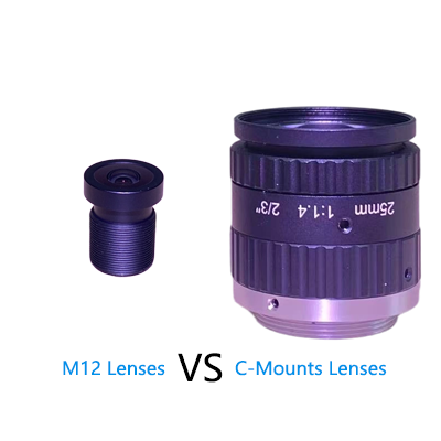
Core definitions of M12 connectors and C-mounts:
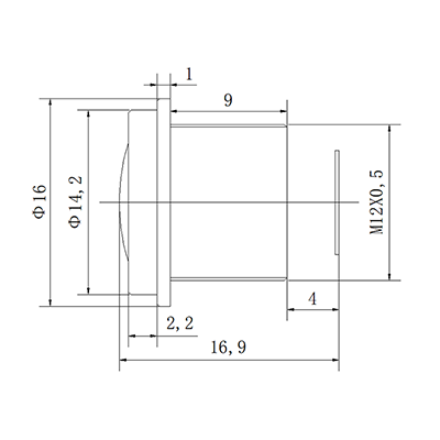
- M12 connector: A small lens connector using M12×0.5 threaded connection. Initially designed for industrial sensors, it is now widely used in embedded vision systems, with compact size and high protection as its core advantages.
- C-mount: A lens connector using 1-inch×32 threaded connection. Derived from the film photography field, it has become one of the standard connectors for industrial vision, characterized by excellent optical compatibility and imaging quality.
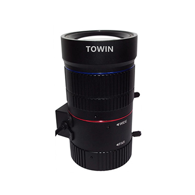
M12 Wide-angle CCTV Lens
Core Features of M12 Connectors and Their Adaptation Potential for Embedded Systems
With its compact structural design, M12 connectors have become the mainstream choice for compact embedded vision systems. Their core features and embedded adaptation potential are as follows:
- Compact mechanical structure: With a connector diameter of only 12mm and a typical length of 10–20mm, it is much smaller than C-mounts. It effectively reduces system volume and fits narrow installation spaces (e.g., micro-cameras, UAV vision modules).
- Standardized thread specifications: Adopts M12×0.5 fine-pitch threads for high connection precision and easy installation. It also has anti-loosening capabilities, making it suitable for batch assembly on automated production lines.
- Rich foolproof designs: Some M12 connectors are equipped with positioning pins or keyway designs to avoid angular deviations during lens installation, ensure optical alignment accuracy, and reduce assembly error costs.
- High environmental protection rating: Most industrial-grade M12 lenses feature IP67/IP68 protection, effectively resisting dust, water, and oil pollution, and adapting to humid and dusty industrial embedded scenarios.
- Significant cost advantages: The production process of M12 lenses and connector modules is mature, with low mass production costs. It is suitable for cost-sensitive compact embedded products (e.g., consumer-grade smart cameras, low-end industrial inspection equipment).
- Compatibility with short focal length lenses: M12 connectors are mainly compatible with short focal length lenses ranging from 2.8mm to 16mm, enabling wide-field imaging to meet the needs of close-range inspection and monitoring in embedded scenarios.
M12 CCTV lens 3-Megapixel IR corrected
M12 vs C-Mount: In-Depth Comparison of Size and Installation Space Compatibility
Size and installation space are the primary considerations for selecting compact embedded vision systems. The following table details the size parameters and installation space compatibility of M12 connectors and C-mounts:
| Comparison Dimension | M12 Connector | C-Mount |
| Connector diameter | 12mm | 25.4mm (1 inch) |
| Standard length | 10–20mm | 30–50mm |
| Thread specification | M12×0.5 (fine pitch) | 1-inch×32 (coarse pitch) |
| Required installation space | Minimal, fits system modules with diameter ≤20mm and length ≤30mm | Large, requires reserved installation space with diameter ≥30mm and length ≥60mm |
| Installation method | Manual tightening without additional tools; suitable for operation in narrow spaces | Requires a wrench for tightening; has certain requirements for operation space |
| Foolproof design | Widely equipped with positioning pins/keyways for high assembly fault tolerance | Foolproof design available on some models, but less popular than M12 connectors |
| Compatibility with compact systems | ★★★★★ | ★★★☆☆ |
C-Mount Core Parameters and Their Adaptation Correlation with Compact Systems
The core parameters of C-mounts directly determine their adaptation potential in compact embedded vision systems. Analysis should be conducted from three dimensions—mechanical size, optical adaptation, and installation accuracy—combining the core requirements of compact systems: small size, high integration, and easy installation.
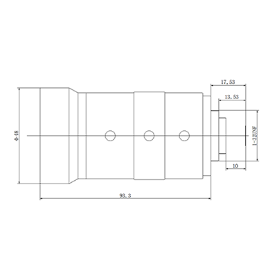
1. Definition of C-Mount Core Parameters
- Flange focal distance: The standard flange focal distance of C-mounts is 17.526mm. This is the fixed distance between the lens mounting surface and the sensor imaging surface, directly affecting optical alignment accuracy. If the overall length needs to be shortened for compact system adaptation, this parameter will limit lens selection.
- Thread specification: 1-inch×32 UN-2A thread with a 60° thread angle and a pitch of 0.7938mm. The long thread engagement length improves connection stability but increases installation space requirements.
- Connector diameter: 25.4mm (1 inch), more than twice the diameter of M12 connectors, which is the core parameter limiting its adaptation to micro-compact systems.
- Back Focal Length (BFL): The BFL of conventional C-mount lenses ranges from 5mm to 15mm. An excessively long BFL increases the axial size of the system, conflicting with the “short axial length” requirement of compact systems.
- Load capacity: Typically compatible with lenses weighing ≤500g. Using small and lightweight C-mount lenses can reduce the structural strength requirements of compact systems.
2. Correlation Table of Core Parameters and Compact System Requirements
| C-Mount Core Parameter | Compact System Requirement | Adaptation Rating | Optimization Suggestions |
| Flange focal distance 17.526mm | Axial size ≤30mm | ★★☆☆☆ | Select short-BFL C-mount lenses or use flange focal distance compensation rings (note the impact on imaging quality) |
| Connector diameter 25.4mm | Radial size ≤20mm | ★☆☆☆☆ | Not recommended for adaptation; prioritize M12 connectors. If necessary, customize miniaturized C-mount adapters |
| Thread length 5mm | Fast installation & small installation space | ★★☆☆☆ | Select C-mount lenses with quick-locking structures to reduce thread engagement length |
| Load capacity ≤500g | Light system weight & simple structure | ★★★★☆ | Match lightweight C-mount lenses weighing ≤300g to simplify the system support structure |
3. Core Adaptation Conclusion
The large diameter and long flange focal distance of C-mounts are inherently conflicting with the “small size” requirement of compact systems. C-mounts can only be adapted by selecting lightweight, short-BFL lenses when compact systems have high image quality requirements (e.g., 4K ultra-high definition, high-precision measurement) and installation space can be moderately relaxed (radial ≥30mm, axial ≥50mm). If the system has strict size constraints, the adaptability of C-mounts is far lower than that of M12 connectors.
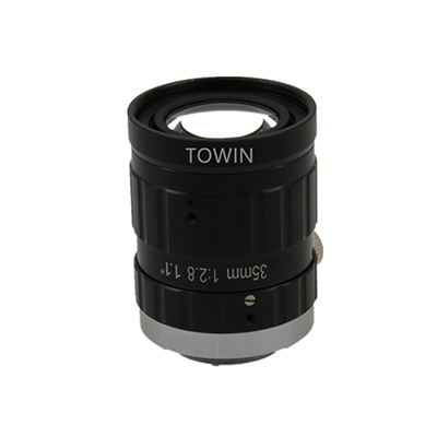
20-35mm-20MP-C-mount-low distortion FA lens-lens
Data Transmission Performance: Adaptation Differences Between M12 and C-Mounts in Embedded Scenarios
In embedded vision systems, in addition to mechanical fixation, some integrated connectors also need to undertake data transmission functions (e.g., M12 Ethernet connectors). The following compares the data transmission performance differences between the two connectors and their adaptability in embedded scenarios:
M12 connector:
- Supports multiple data transmission types: In addition to lens connection, M12 connectors can integrate Ethernet (e.g., M12 X-coded, D-coded), USB, and HDMI data transmission functions, realizing an integrated design of “lens connection + data transmission”. This simplifies system wiring and meets the integration needs of compact embedded systems.
- Transmission rate adaptation: Industrial-grade M12 Ethernet connectors support 10Gbps rates, meeting the real-time transmission needs of high-definition (1080P) and ultra-high-definition (4K) images, and adapting to high-speed embedded vision inspection scenarios.
- Transmission stability: Adopts a shielded design with strong electromagnetic interference (EMI) resistance, suitable for complex electromagnetic environments in industrial embedded scenarios.
C-mount:
- Core function is mechanical fixation: Traditional C-mounts only undertake mechanical connection and optical alignment between the lens and the sensor, without data transmission functions. Additional data transmission interfaces (e.g., USB, GigE) are required, increasing system integration complexity and volume.
- No integrated transmission advantages: Although some new C-mounts can be matched with transmission modules, they have high costs and are not suitable for compact embedded systems.
Summary of Data Transmission Performance Adaptation
| Scenario Requirement | Recommended Connector | Core Reason |
| Compact integration & integrated transmission | M12 connector | Integrated transmission function simplifies wiring and reduces system volume |
| High-speed & high-definition image transmission | M12 connector (Ethernet type) | Supports 10Gbps rate and has strong anti-interference capability |
| Traditional vision system & non-integrated transmission needs | C-mount | Compatible with traditional lenses and has controllable costs (additional transmission modules required) |
Environmental Adaptability: Durability of M12 and C-Mounts in Industrial Embedded Scenarios
Industrial embedded vision systems often face harsh environments such as high temperature, low temperature, humidity, dust, and vibration. The environmental durability of connectors directly determines the long-term reliability of the system. The following compares the environmental adaptability of M12 and C-mounts:
| Environmental Indicator | M12 Connector | C-Mount |
| Protection rating | IP67/IP68 as standard; some models reach IP69K (resistant to high-pressure washing) | IP54/IP55 as standard; additional protective sleeves required to achieve IP67+ |
| Operating temperature range | -40℃~+85℃ (industrial grade) | -20℃~+70℃ (conventional); industrial-grade models can extend to -40℃~+85℃ but with high costs |
| Vibration resistance | Vibration frequency 10–2000Hz, acceleration 10g, high connection stability | Vibration frequency 10–1000Hz, acceleration 5g; additional reinforcement required for strong vibration scenarios |
| Corrosion resistance | Made of stainless steel/special plastic with strong resistance to acid, alkali, and oil pollution | Conventional material is aluminum alloy with general corrosion resistance; surface treatment required |
| Adaptability to industrial embedded scenarios | ★★★★★ | ★★★☆☆ |
Core Conclusion: In industrial embedded scenarios (e.g., automated production lines, outdoor monitoring, vision modules for mining equipment), M12 connectors have significantly better environmental adaptability than C-mounts and can work stably without additional protective measures. C-mounts need to be used with protective accessories, resulting in higher adaptation costs.
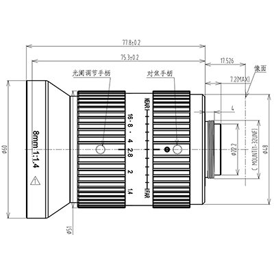
1.1″ C-Mount 8mm Low distortion Wide-angle lens
Optical Performance
Optical performance is the core competitiveness of embedded vision systems. Connectors indirectly determine imaging quality by affecting lens compatibility range and optical alignment accuracy. The following compares the optical performance of M12 and C-mounts from three dimensions: focal length range, aperture size, and image quality.
1. Focal Length Range Comparison: Short Focal Length Advantage of M12 vs Long Focal Length Advantage of C-Mount
M12 connector:
- Compatible focal length range: 2.8mm~16mm, mainly short focal length lenses.
- Core advantage: Short focal length lenses enable wide-field imaging, suitable for close-range imaging scenarios (e.g., product surface defect inspection, face recognition, in-vehicle monitoring).
- Limitation: Cannot be compatible with medium-to-long focal length lenses >16mm, making it difficult to meet long-distance imaging needs (e.g., outdoor long-distance monitoring, large equipment positioning).
C-mount:
- Compatible focal length range: 4mm~100mm+, covering short, medium, and long focal lengths.
- Core advantage: Compatible with long focal length lenses to achieve long-distance, narrow-field imaging, suitable for high-precision measurement and long-distance target recognition (e.g., power inspection, port container recognition).
- Flexibility: Supports various optical lenses such as zoom lenses and macro lenses, with strong optical compatibility.
2. Aperture Size Comparison: Impact of Different Apertures on Imaging Effect
Aperture size determines lens light intake and depth of field, directly affecting low-light imaging quality and image sharpness:
| Connector Type | Maximum Aperture of Compatible Lenses | Low-Light Imaging Effect | Depth of Field Control Capability |
| M12 connector | f/1.2~f/2.0 (conventional); some professional models reach f/0.95 | Moderate light intake; noise easily occurs in low-light environments; supplementary lighting equipment required | Deep depth of field, suitable for close-range, wide-field inspection (e.g., flat surface defect inspection) |
| C-mount | f/0.7~f/1.2 (conventional); professional lenses reach f/0.5 | High light intake; excellent low-light imaging quality with good noise control | Flexible depth of field control; shallow depth of field (highlighting targets) can be achieved with large apertures, or deep depth of field (panoramic clarity) with small apertures |
3. Image Quality Evaluation: Impact of Connectors on Vignetting, Distortion, and Other Issues
Core image quality evaluation indicators include vignetting, geometric distortion, resolution, and contrast. The optical design precision of connectors directly affects these indicators:
Vignetting:
- M12 connector: Due to the small lens size and limited optical design, some short focal length lenses are prone to vignetting (darkening of image edges), which needs to be corrected by image algorithms.
- C-mount: Sufficient optical design space for lenses results in insignificant vignetting. Especially for mid-to-high-end C-mount lenses, uniform full-frame imaging can be achieved.
Geometric distortion:
- M12 connector: Short focal length lenses are prone to barrel distortion (image center bulging outward), with a distortion rate typically ranging from 5% to 15%, requiring algorithm correction.
- C-mount: Wide lens focal length selection range; the distortion rate of medium-to-long focal length lenses can be controlled within 1% to 5%, with better adaptability to high-precision measurement scenarios.
Resolution and contrast:
- M12 connector: Conventional lenses have a resolution of 100–200 lp/mm and moderate contrast, suitable for general inspection scenarios. Professional M12 lenses can reach a resolution of 300 lp/mm but with high costs.
- C-mount: Conventional lenses have a resolution of 200–400 lp/mm and high contrast, compatible with 4K and 8K ultra-high-definition image sensors to meet the needs of high-precision vision inspection.
12-120mm low-distortion C mount lens
Typical Application Scenarios: Adaptation Priority Division of M12 and C-Mounts
Based on the above comparisons, the following divides the adaptation priorities of M12 and C-mounts according to application scenarios to facilitate quick selection:
Scenarios for Prioritizing M12 Connectors
- Compact embedded vision modules: Such as micro-cameras, UAV vision systems, in-vehicle surround-view cameras, and smart door lock cameras.
- Close-range inspection scenarios: Product surface defect inspection (e.g., electronic component solder joint inspection, packaging and printing defect inspection), face recognition, and elevator monitoring.
- Harsh industrial environments: High-temperature and high-humidity workshops, mining equipment, and outdoor monitoring equipment exposed to wind and rain.
- Cost-sensitive projects: Consumer-grade smart hardware and low-end industrial inspection equipment (with general image quality requirements).
- Integrated transmission needs: Vision systems requiring integrated Ethernet and USB data transmission.
Scenarios for Prioritizing C-Mounts
- High-precision measurement scenarios: Such as part dimension measurement, geometric tolerance inspection, and 3D vision scanning.
- Long-distance imaging scenarios: Outdoor long-distance monitoring (e.g., border control, port monitoring), power inspection UAVs, and large equipment positioning.
- High image quality demand scenarios: Ultra-high-definition video capture (4K/8K), medical imaging equipment, and professional industrial inspection (e.g., semiconductor wafer inspection).
- Zoom/macro imaging needs: Vision systems requiring zoom lenses and macro lenses (e.g., biological sample observation, precision part inspection).
- Traditional vision system upgrades: Scenarios with abundant existing C-mount lens libraries requiring compatibility with existing lenses.
FAQs
Q1: Can M12 connectors and C-mounts be interchanged?
No, direct interchange is not possible due to different thread specs, flange focal distances, and sizes, preventing normal imaging. Special adapters (e.g., M12 to C-mount) enable compatibility but add system volume and may degrade image quality (e.g., worse vignetting), recommended only for temporary use.
Q2: Does M12 connector image quality meet industrial inspection needs in compact embedded systems?
It depends on requirements. Professional M12 lenses (≥200 lp/mm) suffice for general surface defects (scratches, stains, missing parts). For high-precision measurement (≤0.01mm) or micro-defects (micron-level scratches), M12 quality is limited; choose C-mount with high-resolution lenses.
Q3: Can M12 connectors withstand outdoor heavy rain?
Yes. Industrial M12 connectors typically have IP67/IP68 ratings: IP67 resists 1m water immersion for 30 mins, IP68 for deeper long-term use. Match lenses/sensors with the same protection to ensure system integrity.
Q4: How much more expensive are C-mount lenses than M12?
Typically 50%-200% more expensive. Conventional M12 lenses: tens-hundreds of yuan; professional M12: <1,000 yuan. C-mount lenses: hundreds-thousands of yuan; high-precision models: >10,000 yuan. C-mount systems also need extra data transmission modules, increasing costs.
Q5: What key indicators matter for embedded vision system selection besides connectors?
Key indicators: 1) Image sensor (resolution, frame rate, pixel size, spectral response); 2) Lens (focal length, aperture, FOV, depth of field); 3) System power consumption; 4) Software compatibility (algorithms, development platforms); 5) Long-term reliability (MTBF); 6) Cost budget (lenses, connectors, sensors).
M12 vs C-Mount
Conclusion
The core logic for selecting M12 connectors and C-mounts in compact embedded vision systems is “space first, image quality second”: If the system has strict size constraints, needs to adapt to harsh environments, or requires cost control, M12 connectors are the optimal choice; if high-precision measurement, long-distance imaging, or high image quality is required, and the installation space is sufficient, C-mounts are more advantageous.
In practical projects, it is recommended to make a comprehensive judgment based on the space constraints, image quality requirements, environmental conditions, and cost budget of specific application scenarios. When necessary, sample tests can be conducted to verify imaging quality and system compatibility.
If you are still unsure whether to choose the M12 or the C-Mount, please download our selection guide or consult our optical engineers.